commsrc.pn
(To be removed) Create PN sequence generator object
Compatibility
commsrc.pn will be removed in a future release. Instead, to generate
a pseudo-noise (PN) sequence, use the comm.PNSequence System object. For more details on the recommended
workflow, see Compatibility Considerations.
Syntax
h = commsrc.pn

h = commsrc.pn(property1,value1,...)
Description
h = commsrc.pn creates a default PN sequence
generator object h, and is equivalent to the following:
H = commsrc.pn('GenPoly',       [1 0 0 0 0 1 1], ...
              'InitialStates', [0 0 0 0 0 1],   ...
              'CurrentStates', [0 0 0 0 0 1],   ...
              'Mask',          [0 0 0 0 0 1],   ...
              'NumBitsOut',    1)
or
H = commsrc.pn('GenPoly',       [1 0 0 0 0 1 1], ...
              'InitialStates', [0 0 0 0 0 1],   ...
              'CurrentStates', [0 0 0 0 0 1],   ...
              'Shift',         0,               ...
              'NumBitsOut',    1)
h = commsrc.pn(property1,value1,...) creates a PN sequence
generator object, h, with properties you specify as property/value
pairs.
Properties
A PN sequence generator has the properties shown on the following table. All properties are writable except for the ones explicitly noted otherwise.
| Property | Description |
|---|---|
| GenPoly | Generator polynomial vector array of bits; must be descending order |
| InitialStates | Vector array (with length of the generator polynomial order) of initial shift register values (in bits) |
| CurrentStates | Vector array (with length of the generator polynomial order) of present shift register values (in bits) |
| NumBitsOut | Number of bits to output at each generate method
invocation |
Mask or Shift | A mask vector of binary 0 and 1 values is used to specify which shift register state bits are XORed to produce the resulting output bit value. Alternatively, a scalar shift value may be used to specify an equivalent shift (either a delay or advance) in the output sequence. |
The 'GenPoly' property values specify the shift register
connections. Enter these values as either a binary vector or a vector of exponents of
the nonzero terms of the generator polynomial in descending order of powers. For the
binary vector representation, the first and last elements of the vector must be 1. For
the descending-ordered polynomial representation, the last element of the vector must be
0. For more information and examples, see the LFSR SSRG Details section of this
page.
Methods
A PN sequence generator is equipped with the following methods.
generate
Generate [NumBitsOut x 1] PN sequence generator values
reset
Set the CurrentStates values to the
InitialStates values
getshift
Get the actual or equivalent Shift property value
getmask
Get the actual or equivalent Mask property value
copy
Make an independent copy of a commsrc.pn object
disp
Display PN sequence generator object properties
Side Effects of Setting Certain Properties
Setting the GenPoly Property
Every time this property is set, it will reset the entire object. In addition to
changing the polynomial values, 'CurrentStates',
'InitialStates', and 'Mask' will be set to
their default values ('NumBitsOut' will remain the same), and no
warnings will be issued.
Setting the InitialStates Property
Every time this property is set, it will also set
'CurrentStates' to the new 'InitialStates'
setting.
LFSR SSRG Details
The generate method produces a pseudorandom noise (PN) sequence
using a linear feedback shift register (LFSR). The LFSR is implemented using a simple
shift register generator (SSRG, or Fibonacci) configuration, as shown below.
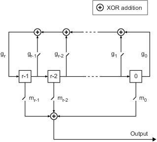
All r registers in the generator update their values at each time
step according to the value of the incoming arrow to the shift register. The adders
perform addition modulo 2. The shift register is described by the
'GenPoly' property (generator polynomial), which is a primitive
binary polynomial in z,
grzr+gr-1zr-1+gr-2zr-2+...+g0.
The coefficient gk is 1 if there is a connection from the kth
register, as labeled in the preceding diagram, to the adder. The leading term
gr and the constant term g0 of the
'GenPoly' property must be 1 because the polynomial must be
primitive.
You can specify the Generator polynomial parameter using either of these formats:
A vector that lists the coefficients of the polynomial in descending order of powers. The first and last entries must be 1. Note that the length of this vector is one more than the degree of the generator polynomial.
A vector containing the exponents of z for the nonzero terms of the polynomial in descending order of powers. The last entry must be
0.
For example, [1 0 0 0 0 0 1 0 1] and [8 2 0]
represent the same polynomial, p(z) = z8 +
z2 + 1.
The Initial states parameter is a vector specifying the initial values of the registers. The Initial states parameter must satisfy these criteria:
All elements of the Initial states vector must be binary numbers.
The length of the Initial states vector must equal the degree of the generator polynomial.
Note
At least one element of the Initial states vector must be nonzero in order for the block to generate a nonzero sequence. That is, the initial state of at least one of the registers must be nonzero.
For example, the following table indicates two sets of parameter values that correspond to a generator polynomial of p(z) = z8 + z2 + 1.
| Quantity | Example 1 | Example 2 |
|---|---|---|
| Generator polynomial | g1 = [1 0 0 0 0 0 1 0 1]
| g2 = [8 2 0]
|
| Degree of generator polynomial | 8, which is length(g1)-1
| 8 |
| Initial states | [1 0 0 0 0 0 1 0]
| [1 0 0 0 0 0 1 0]
|
Output mask vector (or scalar shift value) shifts the starting point of the output sequence. With the default setting for this parameter, the only connection is along the arrow labeled m0, which corresponds to a shift of 0. The parameter is described in greater detail below.
You can shift the starting point of the PN sequence with Output mask vector (or scalar shift value). You can specify the parameter in either of two ways:
An integer representing the length of the shift
A binary vector, called the mask vector, whose length is equal to the degree of the generator polynomial
The difference between the block's output when you set Output mask vector (or scalar shift value) to 0, versus a positive integer d, is shown in the following table.
| T = 0 | T = 1 | T = 2 | ... | T = d | T = d+1 | |
|---|---|---|---|---|---|---|
| Shift = 0 | x0 | x1 | x2 | ... | xd | xd+1 |
| Shift = d | xd | xd+1 | xd+2 | ... | x2d | x2d+1 |
Alternatively, you can set Output mask vector (or scalar shift
value) to a binary vector, corresponding to a polynomial in z,
mr-1zr-1 +
mr-2zr-2 + ... +
m1z + m0, of degree at most r-1. The
mask vector corresponding to a shift of d is the vector that represents m(z) =
zd modulo g(z), where
g(z) is the generator polynomial. For example, if the degree of
the generator polynomial is 4, then the mask vector corresponding to d = 2 is
[0 1 0 0], which represents the polynomial m(z) =
z2. The preceding schematic diagram shows how
Output mask vector (or scalar shift value) is implemented when
you specify it as a mask vector. The default setting for Output mask vector
(or scalar shift value) is 0. You can calculate the
mask vector using the Communications Toolbox™ function shift2mask.
Sequences of Maximum Length
If you want to generate a sequence of the maximum possible length for a fixed degree, r, of the generator polynomial, you can set Generator polynomial to a value from the following table. See Proakis, John G., Digital Communications, Third edition, New York, McGraw Hill, 1995 for more information about the shift-register configurations that these polynomials represent.
| r | Generator Polynomial | r | Generator Polynomial |
|---|---|---|---|
| 2 | [2 1 0]
| 21 | [21 19 0]
|
| 3 | [3 2 0]
| 22 | [22 21 0]
|
| 4 | [4 3 0]
| 23 | [23 18 0]
|
| 5 | [5 3 0]
| 24 | [24 23 22 17 0]
|
| 6 | [6 5 0]
| 25 | [25 22 0]
|
| 7 | [7 6 0]
| 26 | [26 25 24 20 0]
|
| 8 | [8 6 5 4 0]
| 27 | [27 26 25 22 0]
|
| 9 | [9 5 0]
| 28 | [28 25 0]
|
| 10 | [10 7 0]
| 29 | [29 27 0]
|
| 11 | [11 9 0]
| 30 | [30 29 28 7 0]
|
| 12 | [12 11 8 6 0]
| 31 | [31 28 0]
|
| 13 | [13 12 10 9 0]
| 32 | [32 31 30 10 0]
|
| 14 | [14 13 8 4 0]
| 33 | [33 20 0]
|
| 15 | [15 14 0]
| 34 | [34 15 14 1 0]
|
| 16 | [16 15 13 4 0]
| 35 | [35 2 0]
|
| 17 | [17 14 0]
| 36 | [36 11 0]
|
| 18 | [18 11 0]
| 37 | [37 12 10 2 0] |
| 19 | [19 18 17 14 0]
| 38 | [38 6 5 1 0] |
| 20 | [20 17 0]
| 39 | [39 8 0] |
| 40 | [40 5 4 3 0]
| 47 | [47 14 0] |
| 41 | [41 3 0]
| 48 | [48 28 27 1 0] |
| 42 | [42 23 22 1 0]
| 49 | [49 9 0] |
| 43 | [43 6 4 3 0]
| 50 | [50 4 3 2 0] |
| 44 | [44 6 5 2 0]
| 51 | [51 6 3 1 0] |
| 45 | [45 4 3 1 0]
| 52 | [52 3 0] |
| 46 | [46 21 10 1 0]
| 53 | [53 6 2 1 0] |
Examples
Typically commsrc.pn is used to output pseudorandom data
streams.
Construct a PN object.
h = commsrc.pn('Shift',0);Output 10 PN bits.
set(h,'NumBitsOut',10);
generate(h)
ans = 10×1
1
0
0
0
0
0
1
0
0
0
Output 10 more PN bits.
generate(h)
ans = 10×1

     0
     1
     1
     0
     0
     0
     1
     0
     1
     0
Reset the object to the initial shift register state values.
reset(h);
Output 4 PN bits.
set(h,'NumBitsOut',4);
generate(h)
ans = 4×1
1
0
0
0
Version History
Introduced in R2009aR2021b: commsrc.pn will be removed in a future release.
commsrc.pn will be removed in a future release. Instead, to
generate a pseudo-noise (PN) sequence, use the comm.PNSequence
System object™.
Replace instances of the commsrc.pn object with a
comm.PNSequence System object. This table shows the mapping
between commsrc.pn properties and comm.PNSequence properties.
commsrc.pn Object Properties | comm.PNSequence System Object
Properties |
|---|---|
GenPoly | Polynomial |
InitialStates | InitialConditions |
Mask | Mask |
NumBitsOut | SamplesPerFrame |
CurrentStates | Not applicable |
Set up a PN sequence generator. Define the polynomial in binary vector format or exponential vector format.
For example, consider this PN sequence generator with a generator polynomial p(z) = z6 + z + 1.

This table shows some typical usages of commsrc.pn and how to
update your code to use comm.PNSequence instead.
| Discouraged Usage | Recommended Replacement |
|---|---|
Define the PN sequence generator. h1 = commsrc.pn('GenPoly',[1 0 0 0 0 1 1], ... 'Mask',[1 1 0 1 0 1]); h2 = commsrc.pn('GenPoly',[1 0 0 0 0 1 1], ... 'Shift',22); mask2shift([1 0 0 0 0 1 1],[1 1 0 1 0 1]) ans = 22 Alternatively,
input h = commsrc.pn('GenPoly',[6 1 0], 'Mask',[1 1 0 1 0 1]) h =
GenPoly: [1 0 0 0 0 1 1]
InitialStates: [0 0 0 0 0 1]
CurrentStates: [0 0 0 0 0 1]
Mask: [1 1 0 1 0 1]
NumBitsOut: 1 | Define the PN sequence generator. h1 = comm.PNSequence('Polynomial',[1 0 0 0 0 1 1], ... 'InitialConditions', ... [1 1 0 1 0 1]); h2 = comm.PNSequence('Polynomial',[1 0 0 0 0 1 1], ... 'Mask',22); mask2shift([1 0 0 0 0 1 1],[1 1 0 1 0 1]) ans = 22 Alternatively,
input the polynomial exponents of h = comm.PNSequence('Polynomial',[6 1 0],... 'InitialConditions',[1 1 0 1 0 1]) h =
comm.PNSequence with properties:
Polynomial: [6 1 0]
InitialConditionsSource: 'Property'
InitialConditions: [1 1 0 1 0 1]
MaskSource: 'Property'
Mask: 0
VariableSizeOutput: false
SamplesPerFrame: 1
ResetInputPort: false
BitPackedOutput: false
OutputDataType: 'double'
|
You can also select a web site from the following list:
Americas
- América Latina (Español)
- Canada (English)
- United States (English)
Europe
- Belgium (English)
- Denmark (English)
- Deutschland (Deutsch)
- España (Español)
- Finland (English)
- France (Français)
- Ireland (English)
- Italia (Italiano)
- Luxembourg (English)
- Netherlands (English)
- Norway (English)
- Österreich (Deutsch)
- Portugal (English)
- Sweden (English)
- Switzerland
- United Kingdom (English)