PHY Simulation of Bluetooth BR/EDR and LE in Presence of Bluetooth, 5G NR, or WLAN Interference
This example shows an end-to-end PHY simulation of Bluetooth® basic rate/enhanced data rate (BR/EDR) and low energy (LE) in the presence of wireless local area network (WLAN), new radio (5G NR), or Bluetooth interference, and, how you can minimize the impact of interference using adaptive frequency hopping (AFH).
Using this example, you can:
Perform Bluetooth BR/EDR and LE end-to-end simulation in the presence of Bluetooth BR/EDR, LE, 5G NR, or WLAN interference.
Perform AFH by classifying the channels as "good" or "bad" based on the packet error rate (PER).
Compute the bit error rate (BER) and signal-to-interference-plus noise ratio (SINR) of the affected packet.
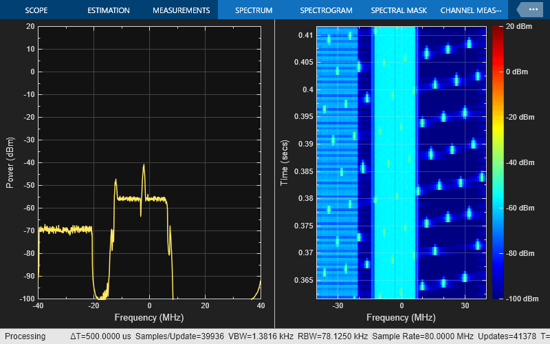
Visualize the spectrum and spectrogram of the Bluetooth BR/EDR or LE waveform in the presence of interference.
Bluetooth, WLAN, and 5G NR Coexistence
Bluetooth operates in the unlicensed 2.4 GHz industrial, scientific, and medical (ISM) band from 2.4 to 2.4835 GHz, which is also used by other technologies such as Zigbee and WLAN. A physical scenario likely contains multiple homogenous and heterogeneous networks operating in this band. To mitigate interference, Bluetooth and WLAN implement AFH and carrier-sense multiple access with collision avoidance (CSMA/CA), respectively. For more information about coexistence between Bluetooth and WLAN, see Bluetooth-WLAN Coexistence.
5G NR unlicensed (5G NR-U) operates in the unlicensed 2.4 GHz and 5 GHz band. 5G NR-U uses Licence Assisted Access (LAA) and Listen Before Talk (LBT) channel access mechanisms to coexist with the incumbent technologies in the ISM band.
AFH enables Bluetooth devices to improve their robustness to interference and avoid interfering with other devices in the 2.4 GHz ISM band. The basic principle of AFH is to classify interference channels as bad channels and discard them from the list of available channels. This classification mechanism of AFH enables a Bluetooth device to use 79 channels or fewer in BR/EDR mode and 40 channels or fewer in LE mode. The Bluetooth Core Specification [2] allows a minimum of 20 channels in BR/EDR mode and 2 channels in LE mode.
This example uses these terminologies:
Affected Wireless Node (AWN)
Bluetooth:
BR
EDR 2Mbps
EDR 3Mbps
LE 1Mbps
LE 2 Mbps
LE 500 Kbps
LE 125 Kbps
Interfering Wireless Node (IWN)
Bluetooth:
BR
EDR 2Mbps
EDR 3Mbps
LE 1Mbps
LE 2 Mbps
LE 500 Kbps
LE 125 Kbps
WLAN:
802.11b with 22 MHz bandwidth
802.11g with 20 MHz bandwidth
802.11n with 20 MHz and 40 MHz bandwidths
802.11ax with 20 MHz and 40 MHz bandwidths
5G NR-U:
5G NR-Downlink (DL) with 10 MHz, 15 MHz, 20 MHz, 25 MHz, 30 MHz, 35 MHz, or 40 MHz bandwidth
Impact of Interference in Space, Time, and Frequency Domains
Space:
As the distance between AWN and IWN nodes increases, the impact of interference in the space domain decreases. In this figure, if d1 and d2 increase, the impact of IWN transmitter interference on the AWN receiver decreases.

Time:
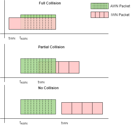
Depending on the packet transmission timings, three possible collision probabilities arise in the time domain: full collision, partial collision, or no collision.
Full : IWN packet completely interferes with the AWN packet.
Partial : IWN packet partially interferes with the AWN packet with the given probability.
No : IWN packet does not interfere with the AWN packet..

Frequency:
As the channel separation between the AWN and IWN nodes increases, the impact of interference in the frequency domain decreases. In this figure, if the difference between and increase, the impact of the IWN transmitter interference on the AWN receiver decreases.
Simulation Parameters
Specify the AWN parameters, such as the signal type, transmitter position, receiver position, transmitter power, and packet type.
Specify frequency hopping as one of these values.
On(default)—To run simulation with AFH, select this value.The example does not configureawnFrequency.Off—To run simulation at fixed frequency, select this value.
awnSignalType ="LE1M"; awnTxPosition =
[0,0,0]; % In meters awnRxPosition =
[10,0,0]; % In meters awnTxPower =
30; % In dBm awnPacket =
"Disabled"; awnFrequencyHopping =
"On"; awnFrequency =
2440*1e6; % In Hz
Configure single or multiple IWNs and their respective parameters, such as the signal type, transmitter position, fixed frequency of operation, and transmitter power. Create and configure multiple IWN nodes by using the IWN structure with different indices.
Specify the collision probability in the range [0, 1]. Any value between 0 and 1 simulates partial collision. To simulate full collision, set this value to 1. To disable interference and simulate with no collisions, set this value to 0.
To add different types of WLAN or 5G NR signals as interference, you must have WLAN Toolbox™ or 5G Toolbox™ respectively. If you do not have WLAN Toolbox or 5G Toolbox, set the SignalType field of an iwn element to WLANBasebandFile to add a WLAN signal or NRDLBasebandFile to add an 5G NR-U DL signal. Because the WLANBasebandFile captures data in a single input single output (SISO) configuration, you must specify the number of transmit antennas, iwn(1).NumWLANTransmitAntennas as 1.
iwn(1).SignalType ="WLANHESUBandwidth20.bb"; iwn(1).TxPosition = [20,0,0]; % In meters iwn(1).Frequency = 2437e6; % In Hz iwn(1).NumWLANTransmitAntennas = 1; % Number of transmit antennas relevant for WLAN signals iwn(1).TxPower = 30; % In dBm iwn(1).CollisionProbability = 1; % Probability of collision in time, must be between [0,1] iwn(1).WLANOverSamplingFactor = 1; % Over sampling factor relevant for WLAN signals iwn(1).NRNumSubFrames = 10; % Number of sub frames relevant for 5G NR signals iwn(1).NRSubCarrierSpacing =
15; % Sub carrier spacing relevant for 5G NR signals iwn(1).NRPRBOccupancy =
100; % Allocation percentage of RBs relevant for 5G NR signals iwn(2).SignalType =
"NRDLBandwidth20.bb"; iwn(2).TxPosition = [25,0,0]; % In meters iwn(2).Frequency = 2410e6; % In Hz iwn(2).NumWLANTransmitAntennas = 1; iwn(2).TxPower = 30; % In dBm iwn(2).CollisionProbability = 0.2; % Probability of collision in time, must be between [0,1] iwn(2).WLANOverSamplingFactor = 1; % over sampling factor relevant for WLAN signals iwn(2).NRNumSubFrames = 10; % Number of sub frames relevant for 5G NR signals iwn(2).NRSubCarrierSpacing =
15; % Sub carrier spacing relevant for 5G NR signals in KHz iwn(2).NRPRBOccupancy =
100; % Allocation percentage of RBs relevant for 5G NR signals
Specify the environment, bit energy to noise density ratio (Eb/No), sample rate, and number of packets.
environment ="Outdoor"; EbNo = 10; % In dB sampleRate = 80e6; % In Hz numPackets = 500; pathlossCfg = bluetoothPathLossConfig(Environment=environment,RandomStream="mt19937ar with seed");
Specify the type of channel model for AWN as "AWGN", "Rician Channel", or "Rayleigh Channel".
awnChannelModel =  "AWGN";
Enable or disable the decision feedback equalizer (DFE) by checking the enableEqualizer flag. Enabling DFE mitigates the effects of the fading channel model on the Bluetooth LE transmit waveforms.
enableEqualizer =  false;
Initialize the random stream.
stream = RandStream("combRecursive");Initialize the RF impairments. To configure the RF impairments, create a variable fractional delay object by using the dsp.VariableFractionalDelay (DSP System Toolbox) System object™. Create and configure phase noise by using the comm.PhaseNoise System object.
timingOffset = randsrc(1,1,1:0.1:100);         % In samples, less than 1 microsecond
freqOffset = randsrc(1,1,-10e3:100:10e3);      % In Hz
phaseNoiseLevel = [-130 -136];                 % In decibels relative to carrier per hertz
phaseFreqOffset = [1e4 1e5];                   % In Hz, must be less than sample rate/2
timingDelay = dsp.VariableFractionalDelay;
phaseNoise = comm.PhaseNoise(Level=phaseNoiseLevel, ...
    FrequencyOffset=phaseFreqOffset, ...
    SampleRate=sampleRate);
Initialize the fading channel model.
if awnChannelModel ~= "AWGN"
    channelInit = helperBluetoothChannelInit(sampleRate,awnChannelModel);
end
Configure the waveform transmission and reception parameters of the AWN.
phyFactor = 1 + 1*(awnSignalType=="LE2M");
spsFac = sampleRate/(1e6*phyFactor);
needResample = spsFac ~= fix(spsFac);
if needResample
    [spsG,~] = rat(spsFac);
else
    spsG = spsFac;
end
if ~needResample                                              % Decimation factor for the receiver filter
    sps = sampleRate/(1e6*phyFactor);
    if sps > 8
        decimationFactor = gcd(sps,8);
    else
        decimationFactor = 1;
     end
else
    newFs = 40e6;
    sps = newFs/(1e6*phyFactor);
    decimationFactor = 8;
end

% Create an automatic gain control (AGC) System object™
agc = comm.AGC(MaxPowerGain=60,DesiredOutputPower=1);
if any(strcmp(awnSignalType,["LE1M","LE2M","LE500K","LE125K"]))
    payloadLength = 100;                                % Length of the payload in bytes
    accessAddress = "F4D26EAC";                         % Access address
    accessAddBits = int2bit(hex2dec(accessAddress),32,false);

    % Derive channel index based on the AWN frequency
    channelIndexArray = [37 0:10 38 11:36 39];
    awnBandwidth = 2e6;
    channelIndex = channelIndexArray((awnFrequency-2402e6)/awnBandwidth+1);

    % Configure the receiver parameters in a structure
    rxCfg = struct(Mode=awnSignalType,SamplesPerSymbol=sps/decimationFactor,ChannelIndex=channelIndex, ...
        DFPacketType=awnPacket,AccessAddress=accessAddBits);
    rxCfg.CoarseFreqCompensator = comm.CoarseFrequencyCompensator(Modulation="OQPSK", ...
        SampleRate=sampleRate/decimationFactor, ...
        SamplesPerSymbol=2*rxCfg.SamplesPerSymbol, ...
        FrequencyResolution=10);
    rxCfg.PreambleDetector = comm.PreambleDetector(Detections="First");
    rxCfg.EqualizerFlag = enableEqualizer;
else
    % Create and configure Bluetooth waveform generation parameters
    awnWaveformConfig = bluetoothWaveformConfig(Mode=awnSignalType,PacketType=awnPacket, ...
        SamplesPerSymbol=spsG);
    if strcmp(awnPacket,"DM1")
        awnWaveformConfig.PayloadLength = 17;            % Maximum length of DM1 packets in bytes
    end
    payloadLength = getPayloadLength(awnWaveformConfig); % Length of the payload

    % Get the receiver configuration parameters
    rxCfg = getPhyConfigProperties(awnWaveformConfig);
    rxCfg.SamplesPerSymbol = sps/decimationFactor;
end
Estimate the distance between the AWN transmitter and AWN receiver, and then compute the path loss between them.
distanceAWNTxRx = sqrt(sum((awnTxPosition-awnRxPosition).^2));
pathlossdB = bluetoothPathLoss(distanceAWNTxRx,pathlossCfg);
awnPathloss = 10^(pathlossdB/20);
Create and configure the IWN by using the helperIWNConfig helper object. Generate IWN waveforms by using the generateIWNWaveform object function. Add the path loss based on the environment and node positions by using the applyPathloss object function. Pass the signal through the fading channel model.
iwnConfig = helperIWNConfig(IWN=iwn,SampleRate=sampleRate, ...
    Environment=environment);
iwnWaveform = generateIWNWaveform(iwnConfig);
[iwnWaveformPL,iwnPathloss] = applyPathloss(iwnConfig,iwnWaveform,awnRxPosition);
if awnChannelModel ~= "AWGN"
    iwnWaveformPL = applyChannel(iwnConfig,iwnWaveformPL,awnRxPosition,awnChannelModel);
end
Use the bluetoothFrequencyHop and bleChannelSelection objects to select a channel index for the transmission and reception of Bluetooth BR/EDR and LE waveforms, respectively.
if strcmp(awnFrequencyHopping,"On")
    if any(strcmp(awnSignalType,["LE1M","LE2M","LE500K","LE125K"]))
        frequencyHop = bleChannelSelection;   % Bluetooth LE channel index System object
        numBTChannels = 37;                   % Number of Bluetooth LE channels
        minChannels = 2;                      % Minimum number of channels to classify
    else
        frequencyHop = bluetoothFrequencyHop; % Bluetooth BR/EDR channel index object
        frequencyHop.SequenceType = "Connection Adaptive";
        numBTChannels = 79;                   % Number of Bluetooth BR/EDR channels
        minChannels = 20;                     % Minimum number of channels to classify
        inputClock = 0;
        numSlots = 1*(any(strcmp(awnPacket,["ID","NULL","POLL","FHS","HV1","HV2", ...
                    "HV3","DV","EV3","DM1","DH1","AUX1","2-DH1","3-DH1","2-EV3","3-EV3"])))...
                    +(3*any(strcmp(awnPacket,["EV4","EV5","DM3","DH3","2-EV5","3-EV5","2-DH3", ...
                    "3-DH3"])))+ (5*any(strcmp(awnPacket,["DM5","DH5","2-DH5","3-DH5"])));
        slotValue = numSlots*2;
        clockTicks = slotValue*2;             % Clock ticks (one slot is two clock ticks)
    end
end
Design a receiver filter to capture the AWN waveform.
if any(strcmp(awnSignalType,["EDR2M","EDR3M"]))
    rolloff = 0.4;
    span = 8;
    filterCoeff = rcosdesign(rolloff,span,sps,"sqrt");
else
    N = 200;                                   % Order
    Fc = 1.5e6/(1+strcmp(awnSignalType,"BR")); % Cutoff frequency
    flag = "scale";                            % Sampling flag
    alpha = 3;                                 % Window parameter

    % Create the window vector for the design algorithm
    win = gausswin(N+1,alpha);

    % Calculate the coefficients using the FIR1 function
    filterCoeff = fir1(N,Fc/(sampleRate/2),"low",win,flag);
end
firdec = dsp.FIRDecimator(decimationFactor,filterCoeff);
Compute the signal-to-noise ratio (SNR).
codeRate = 1*any(strcmp(awnSignalType,["LE1M","LE2M"]))+1/2*strcmp(awnSignalType,"LE500K")+1/8*strcmp(awnSignalType,"LE125K")+...
    any(strcmp(awnSignalType,["BR","EDR2M","EDR3M"]))*(1-2/3*strcmp(awnPacket,"HV1")-...
    1/3*any(strcmp(awnPacket,["FHS","DM1","DM3","DM5","HV2","DV","EV4"])));           % Code rate
bitsPerSymbol = 1+ strcmp(awnSignalType,"EDR2M") + 2*(strcmp(awnSignalType,"EDR3M")); % Number of bits per symbol
snr = EbNo + 10*log10(codeRate) + 10*log10(bitsPerSymbol) - 10*log10(sps);
Create and configure the spectrum analyzer to visualize the spectrum and spectrogram of the Bluetooth BR/EDR or LE waveform in the presence of interference.
specAn = spectrumAnalyzer(...
    Name="Bluetooth Coexistence Modeling", ...
    ViewType="Spectrum and spectrogram", ...
    TimeResolutionSource="Property", ...
    TimeResolution=0.0005, ...
    SampleRate=sampleRate, ...
    TimeSpanSource="Property", ...
    TimeSpan=0.05, ...
    FrequencyResolutionMethod="num-frequency-bands" , ...
    FFTLengthSource="property", ...
    AxesLayout="Horizontal", ...
    YLimits=[-100 20], ...
    ColorLimits=[-100 20]);
End-to-end Simulation
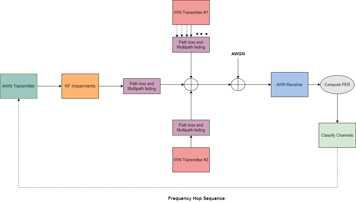
This diagram summarizes the example workflow.

Perform these steps to simulate the coexistence scenario.
Generate AWN (Bluetooth BR/EDR or LE) waveforms.
Distort each AWN waveform with these RF impairments: timing offset, carrier frequency offset, and DC offset.
Hop the waveform (frequency shift based on a center frequency of 2440 MHz) using the channel index derived from AFH.
Scale the hopped waveform with the transmitter power and path loss.
Generate and add IWN waveforms (Bluetooth BR/EDR, LE, WLAN or 5G NR) based on the collision probabilities.
Pass the AWN and IWN waveforms through their respective fading channels.
Add additive white Gaussian noise (AWGN) to the combined signal.
Filter the noisy waveform.
Recover the bits from the filtered waveform by performing timing synchronization, carrier frequency offset correction, DC offset correction and equalization.
Compute the PER, BER, and SINR.
If frequency hopping is on, classify the channels.
% Classify the channels for every |numPacketsToClassify| packets. If the PER of the
% channel is greater than |thresholdPER|, then map the corresponding channel
% as bad.
numPacketsToClassify = 50;
thresholdPER = 0.2;

% Create an instance of the error rate
errorRate = comm.ErrorRate;

% Initialize variables to perform the simulation
numErrors = 0;
numPktLost = 0;
countPER = 0;
countPreviousPER = 0;
midFrequency = 2440e6;
if strcmp(awnFrequencyHopping,"On")
    errorsBasic = deal(zeros(numBTChannels,3));
    errorsBasic(:,1) = (0:numBTChannels-1);
end

% Number of interfering nodes that collide with AWN
collisionCount = 0;
for index = 1:iwnConfig.NumIWNNodes
    collisionCount = collisionCount + (iwn(index).CollisionProbability > 0);
end

if strcmp(awnFrequencyHopping,"On") && collisionCount ~= 0
    sinr = zeros(numPackets,1);
end

% Loop to simulate multiple packets
for inum = 1:numPackets

     stream.Substream = inum;
     RandStream.setGlobalStream(stream);

    % Generate AWN waveform
    if any(strcmp(awnSignalType,["LE1M","LE2M","LE500K","LE125K"]))
        if strcmp(awnFrequencyHopping,"On")
            channelIndex = frequencyHop();
            channelFrequencies = [2404:2:2424 2428:2:2478 2402 2426 2480]*1e6;
            awnFrequency = channelFrequencies(channelIndex + 1);
        end
        txBits = randi([0 1],payloadLength*8,1,"int8");
        awnWaveform = bleWaveformGenerator(int8(txBits),Mode=awnSignalType,ChannelIndex=channelIndex, ...
            SamplesPerSymbol=spsG,AccessAddress=accessAddBits,DFPacketType=awnPacket);

    else
        if strcmp(awnFrequencyHopping,"On")
            inputClock = inputClock + clockTicks;

            % Frequency hopping
            channelIndex = nextHop(frequencyHop,inputClock)
            awnFrequency = (2402 + channelIndex)*1e6;

            % Generate whiten initialization vector from clock
            clockBinary = int2bit(inputClock,28,false).';
            awnWaveformConfig.WhitenInitialization = [clockBinary(2:7)'; 1];
        end
        txBits = randi([0 1],payloadLength*8,1);
        awnWaveform = bluetoothWaveformGenerator(txBits,awnWaveformConfig);
    end
    if needResample
        [p,q] = rat(spsFac/(spsG*phyFactor));
        awnWaveform = resample(awnWaveform,p,q);
    end
    % Add timing offset
    timingOffsetWaveform = timingDelay(awnWaveform,timingOffset);

    % Add frequency offset
    freqOffsetWaveform = frequencyOffset(timingOffsetWaveform,sampleRate,freqOffset);

    % Add DC offset
    dcValue = (5/100)*max(freqOffsetWaveform);
    dcWaveform = freqOffsetWaveform + dcValue;

    % Add phase noise
    txImpairedWaveform = phaseNoise(dcWaveform);

    % Scale the waveform as per the transmitter power and path loss
    soiAmplitudeLinear = 10^((awnTxPower - 30)/20)/awnPathloss;
    attenAWNWaveform = soiAmplitudeLinear*txImpairedWaveform;

    if (awnChannelModel == "AWGN")
        txChanWfm = attenAWNWaveform;
    else
        % Fading channel filter delay
        chanDelay = info(channelInit.fadingChan).ChannelFilterDelay;

        % Pass through the fading channel model
        txChanWfm = channelInit.fadingChan([attenAWNWaveform; zeros(chanDelay,1)]);
        txChanWfm = txChanWfm(chanDelay+1:end,1);
    end

    % Add IWN waveform to AWN waveform
    addIWN2AWN = addInterference(iwnConfig,txChanWfm,iwnWaveformPL,awnFrequency);
    freqOffsetWaveform = frequencyOffset(addIWN2AWN,sampleRate,2440e6-awnFrequency);

    % Add AWGN
    soiPower = 20*log10(soiAmplitudeLinear);
    noisePower = soiPower - snr;
    splusibyn = 10*log10(var(freqOffsetWaveform)) - noisePower;
    noisyWaveform = awgn(freqOffsetWaveform,splusibyn,"measured");

    % Apply filter
    if needResample
        [P,Q] = rat(newFs/sampleRate);
        noisyWaveform = resample(noisyWaveform,P,Q);
    end
    if rem(numel(noisyWaveform),sps)
        remainder = sps-rem(numel(noisyWaveform),sps);
        noisyWaveform = [noisyWaveform; zeros(remainder,1)]; %#ok<AGROW>
    end
    delay = floor(numel(firdec.Numerator)/(2*decimationFactor));
    noisyWaveformPadded = [noisyWaveform;zeros(delay*decimationFactor,1)];
    filteredWaveform = firdec(noisyWaveformPadded);
    release(firdec)
    filteredWaveform = filteredWaveform(1+delay:end)*sqrt(decimationFactor);
    filteredWaveform = agc(filteredWaveform);

    % Recover the data bits
    if any(strcmp(awnSignalType,["LE1M","LE2M","LE500K","LE125K"]))
        rxCfg.ChannelIndex = channelIndex;
        [rxBits,accAddress] = helperBLEPracticalReceiver(filteredWaveform,rxCfg);
        if isempty(rxBits) || ~isequal(accessAddBits,accAddress)
            pktStatus = [];
        end
    else
        % Get PHY properties
        rxCfg.WhitenInitialization = awnWaveformConfig.WhitenInitialization;
        [rxBits,~,pktStatus] ...
            = helperBluetoothPracticalReceiver(filteredWaveform,rxCfg);
    end
Simulation Results
Compute the BER and PER for each packet. If frequency hopping has been enabled,
Perform channel classification for every
numPacketsToClassifybased on the PER.Compute the SINR for each packet.
Visualize the Bluetooth BR/EDR or LE waveform with the interference.
    % Compute BER and PER
    lengthTx = length(txBits);
    lengthRx = length(rxBits);
    lengthMinimum = min(lengthTx,lengthRx) - 1;
    countPreviousPER = countPER;
    if lengthTx && lengthRx
        vectorBER = errorRate(txBits(1:lengthMinimum),rxBits(1:lengthMinimum));
        currentErrors = vectorBER(2) - numErrors;    % Number of errors in current packet
        if currentErrors                             % Check if current packet is in error or not
            countPER  = countPER + 1;                % Increment the PER count
        end
        numErrors = vectorBER(2);
    elseif ~isempty(pktStatus)
        countPER  = countPER + ~pktStatus;           % Increment the PER count
    else
        numPktLost = numPktLost+1;
    end

    % Perform frequency hopping
    if strcmp(awnFrequencyHopping,"On")
        chIdx = channelIndex + 1;
        if countPreviousPER ~= countPER
            errorsBasic(chIdx,3) = errorsBasic(chIdx,3) + 1;
        end

        % Classify the channels
        if any(inum == (1:floor(numPackets/numPacketsToClassify))*numPacketsToClassify)
            channelMap = errorsBasic(:,3)/numPacketsToClassify > thresholdPER;
            if nnz(channelMap) == 0
                continue;
            end
            badChannels = find(channelMap) - 1;
            if length(frequencyHop.UsedChannels)-length(badChannels) < minChannels
                errorsBasic(badChannels+1,3) = 0;
                usedChannels = 0:36;
            else
                errorsBasic(badChannels+1,3) = 0;
                usedChannels = setdiff(frequencyHop.UsedChannels,badChannels);
            end
            frequencyHop.UsedChannels = usedChannels;
        end
    end

    % Visualize the spectrum and spectrogram. Compute SINR.
    if strcmp(awnFrequencyHopping,"On") && collisionCount ~= 0
        sinr(inum) = helperBluetoothSINREstimate(snr,awnTxPower,awnFrequency,pathlossdB,iwnConfig,iwnPathloss);
        specAn(addIWN2AWN)
    elseif (strcmp(awnFrequencyHopping,"Off") && inum<70) || (strcmp(awnFrequencyHopping,"On") && collisionCount == 0)
        if inum == 1
            sinr = helperBluetoothSINREstimate(snr,awnTxPower,awnFrequency,pathlossdB,iwnConfig,iwnPathloss);
        end
        specAn(addIWN2AWN)
    end

    if (awnChannelModel ~= "AWGN")
        reset(channelInit.fadingChan);
    end
end

if ~any(strcmp(awnPacket,["ID","NULL","POLL"]))
    if numPackets ~= numPktLost
        per = countPER/(numPackets - numPktLost);
        ber = vectorBER(1);
        fprintf('Mode %s, Simulated for Eb/No = %d dB, Obtained BER: %d, Obtained PER: %d\n',awnSignalType,EbNo,ber,per);
    else
        fprintf('No Bluetooth packets were detected.\n');
        per = 1;
        ber = 1;
    end
else
    if numPackets ~= numPktLost
        per = countPER/(numPackets-numPktLost);
        fprintf('Mode %s, Simulated for Eb/No = %d dB, Obtained PER: %d\n',awnSignalType,EbNo,per);
    else
        fprintf('No Bluetooth packets were detected.\n');
    end
end
Mode LE1M, Simulated for Eb/No = 10 dB, Obtained BER: 8.771930e-05, Obtained PER: 3.400000e-02
Further Exploration
To observe the PER performance relative to interferer distance, you can run the simulation for different IWN transmitter positions. This plot shows the impact of interferer distance on PER given:
Bluetooth LE1M AWN, 10 meters distance between the AWN transmitter and receiver, an AWN frequency of 2440 MHz, and an Eb/No value of 10 dB.
802.11g with 20 MHz bandwidth IWN, an IWN frequency of 2437 MHz (co-channel interference), and a collision probability of 1.

To observe the PER performance relative to interferer channel separation, you can run the simulation for different IWN frequencies (when frequency hopping is off). This plot shows the impact of interferer channel separation on PER given:
Bluetooth LE1M AWN, 10 m distance between the AWN transmitter and receiver, and an Eb/No value of 10 dB.
802.11g with 20 MHz bandwidth IWN, an IWN frequency of 2437 MHz, a collision probability of 1, and 10 m distance between the AWN and IWN transmitters.

To observe the PER performance relative to collision probability, you can run the simulation for different collision probabilities. This plot shows the impact of collision probability on PER by considering:
Bluetooth LE1M AWN, an AWN frequency of 2440 MHz, 10 m between the AWN transmitter and receiver, and an Eb/No value of 10 dB.
802.11g with 20 MHz bandwidth IWN, an IWN frequency of 2437 MHz, and 10 m between the AWN and IWN transmitters.

Appendix
The example uses these helper functions:
helperIWNConfig—Interference wireless node configuration parametershelperBluetoothChannelInit—Initialize fading channel parametershelperBLEPracticalReceiver—Demodulate and decode the received signalhelperBluetoothPracticalReceiver—Detect, synchronize, and decode the received Bluetooth BR/EDR waveformhelperBluetoothSINREstimate—Estimate SINR
Selected Bibliography
Bluetooth Technology Website. “Bluetooth Technology Website | The Official Website of Bluetooth Technology.” Accessed November 15, 2024. https://www.bluetooth.com.
Bluetooth Special Interest Group (SIG). "Core System Package [Low Energy Controller Volume]". Bluetooth Core Specification. Version 5.3, https://www.bluetooth.com.
Siraj Muhammad, Mohamad Omar Al Kalaa, and Hazem H, "Wireless Coexistence of Cellular LBT Systems and BLE 5", IEEE Access. Vol 9