TuningGoal.Overshoot
Overshoot constraint for control system tuning
Description
Use TuningGoal.Overshoot to limit the overshoot in
the step response from specified inputs to specified outputs of a control system. Use this tuning
goal for control system tuning with tuning commands such as systune or
looptune.
Creation
Description
Req = TuningGoal.Overshoot(inputname,outputname,maxpercent)maxpercent specifies the maximum overshoot
as a percentage.
When you use TuningGoal.Overshoot for tuning, the
software maps overshoot constraints to peak gain constraints assuming second-order system
characteristics. Therefore, the mapping is only approximate for higher-order systems. In
addition, this tuning goal cannot reliably reduce the overshoot below 5%.
Input Arguments
Input signals for the tuning goal, specified as a character vector or, for multiple-input tuning goals, a cell array of character vectors.
If you are using the tuning goal to tune a Simulink® model of a control system, then
inputnamecan include:Any model input.
Any linear analysis point marked in the model.
Any linear analysis point in an
slTuner(Simulink Control Design) interface associated with the Simulink model. UseaddPoint(Simulink Control Design) to add analysis points to theslTunerinterface. UsegetPoints(Simulink Control Design) to get the list of analysis points available in anslTunerinterface to your model.
For example, suppose that the
slTunerinterface contains analysis pointsu1andu2. Use'u1'to designate that point as an input signal when creating tuning goals. Use{'u1','u2'}to designate a two-channel input.
If you are using the tuning goal to tune a generalized state-space (
genss) model of a control system, theninputnamecan include:Any input of the
genssmodelAny
AnalysisPointlocation in the control system model
For example, if you are tuning a control system model,
T, theninputnamecan be any input name inT.InputName. Also, ifTcontains anAnalysisPointblock with a location namedAP_u, theninputnamecan include'AP_u'. UsegetPointsto get a list of analysis points available in agenssmodel.If
inputnameis anAnalysisPointlocation of a generalized model, the input signal for the tuning goal is the implied input associated with theAnalysisPointblock:
For more information about analysis points in control system models, see Mark Signals of Interest for Control System Analysis and Design.
Output signals for the tuning goal, specified as a character vector or, for multiple-output tuning goals, a cell array of character vectors.
If you are using the tuning goal to tune a Simulink model of a control system, then
outputnamecan include:Any model output.
Any linear analysis point marked in the model.
Any linear analysis point in an
slTuner(Simulink Control Design) interface associated with the Simulink model. UseaddPoint(Simulink Control Design) to add analysis points to theslTunerinterface. UsegetPoints(Simulink Control Design) to get the list of analysis points available in anslTunerinterface to your model.
For example, suppose that the
slTunerinterface contains analysis pointsy1andy2. Use'y1'to designate that point as an output signal when creating tuning goals. Use{'y1','y2'}to designate a two-channel output.
If you are using the tuning goal to tune a generalized state-space (
genss) model of a control system, thenoutputnamecan include:Any output of the
genssmodelAny
AnalysisPointlocation in the control system model
For example, if you are tuning a control system model,
T, thenoutputnamecan be any output name inT.OutputName. Also, ifTcontains anAnalysisPointblock with a location namedAP_u, thenoutputnamecan include'AP_u'. UsegetPointsto get a list of analysis points available in agenssmodel.If
outputnameis anAnalysisPointlocation of a generalized model, the output signal for the tuning goal is the implied output associated with theAnalysisPointblock:
For more information about analysis points in control system models, see Mark Signals of Interest for Control System Analysis and Design.
maxpercent — Maximum percent overshoot
scalar
Maximum percent overshoot, specified as a scalar value. For example, the following code
specifies a maximum 5% overshoot in the step response from 'r' to
'y'.
Req = TuningGoal.Overshoot('r','y',5);
TuningGoal.OverShoot cannot reliably reduce the overshoot below 5%.
Properties
Examples
Overshoot Constraint
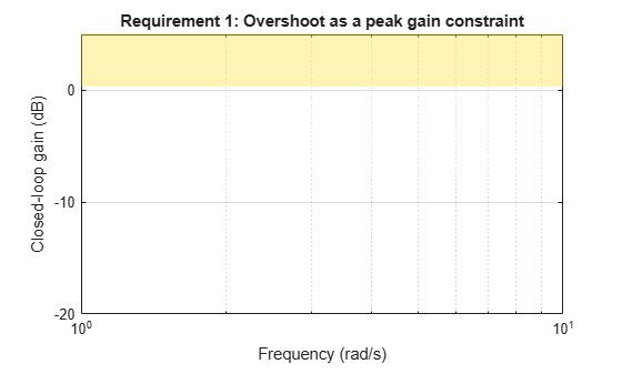
Create a tuning goal that limits the overshoot of the step response from signals named 'r' to 'y' in a control system to 10 percent.
Req = TuningGoal.Overshoot('r','y',10);
The overshoot tuning goal is evaluated as a constraint on the peak system gain, assuming second-order model characteristics (see Algorithms). Visualizing the tuning goal shows a shaded area where the target peak gain is exceeded.
viewGoal(Req)
If you visualize the tuning goal with a tuned system, the plot includes the corresponding system response.
Configure other characteristics of the tuning goal by setting properties. For instance, configure the tuning goal to apply only to the second model in a model array to tune. Also, configure it to be evaluated with a loop open at an analysis point in the control system called OuterLoop.
Req.Models = 2;
Req.Openings = 'OuterLoop';
Tips
This tuning goal imposes an implicit stability constraint on the closed-loop transfer function from
InputtoOutput, evaluated with loops opened at the points identified inOpenings. The dynamics affected by this implicit constraint are the stabilized dynamics for this tuning goal. TheMinDecayandMaxRadiusoptions ofsystuneOptionscontrol the bounds on these implicitly constrained dynamics. If the optimization fails to meet the default bounds, or if the default bounds conflict with other requirements, usesystuneOptionsto change these defaults.
Algorithms
When you tune a control system using a TuningGoal, the software converts
the tuning goal into a normalized scalar value f(x).
x is the vector of free (tunable) parameters in the control system. The
software then adjusts the parameter values to minimize
f(x), or to drive
f(x) below 1 if the tuning goal is a hard
constraint.
For TuningGoal.Overshoot,
f(x) reflects the relative satisfaction or violation of
the goal. The percent deviation from f(x) = 1 roughly
corresponds to the percent deviation from the specified overshoot target. For example,
f(x) = 1.2 means the actual overshoot exceeds the target
by roughly 20%, and f(x) = 0.8 means the actual overshoot
is about 20% less than the target.
TuningGoal.Overshoot uses as a proxy for the overshoot, based on second-order model characteristics.
Here, T is the closed-loop transfer function that the tuning goal constrains.
The overshoot is tuned in the range from 5% ( = 1) to 100% (). TuningGoal.Overshoot is ineffective at
forcing the overshoot below 5%.
Version History
Introduced in R2016aSee Also
looptune | systune | systune (for slTuner) (Simulink Control Design) | looptune (for slTuner) (Simulink Control Design) | viewGoal | evalGoal | TuningGoal.Gain | TuningGoal.Sensitivity | slTuner (Simulink Control Design)
You can also select a web site from the following list:
Americas
- América Latina (Español)
- Canada (English)
- United States (English)
Europe
- Belgium (English)
- Denmark (English)
- Deutschland (Deutsch)
- España (Español)
- Finland (English)
- France (Français)
- Ireland (English)
- Italia (Italiano)
- Luxembourg (English)
- Netherlands (English)
- Norway (English)
- Österreich (Deutsch)
- Portugal (English)
- Sweden (English)
- Switzerland
- United Kingdom (English)