TuningGoal.Rejection
Disturbance rejection requirement for control system tuning
Description
Use TuningGoal.Rejection to specify the minimum
attenuation of a disturbance injected at a specified location in a control system. This tuning
goal helps you tune control systems with tuning commands such as systune or
looptune.
When you use TuningGoal.Rejection, the software attempts
to tune the system so that the attenuation of a disturbance at the specified location exceeds the
minimum attenuation factor you specify. This attenuation factor is the ratio between the open-
and closed-loop sensitivities to the disturbance and is a function of frequency. You can achieve
disturbance attenuation only inside the control bandwidth. The loop gain must be larger than one
for the disturbance to be attenuated (attenuation factor > 1).
Creation
Description
Input Arguments
distloc — Disturbance location
character vector | cell array of character vectors
Disturbance location, specified as a character vector or, for multiple-input tuning goals, a cell array of character vectors.
If you are using the tuning goal to tune a Simulink® model of a control system, then
distloccan include any signal identified as an analysis point in anslTuner(Simulink Control Design) interface associated with the Simulink model. UseaddPoint(Simulink Control Design) to add analysis points to theslTunerinterface. UsegetPoints(Simulink Control Design) to get the list of analysis points available in anslTunerinterface to your model.For example, suppose that the
slTunerinterface contains analysis pointsu1andu2. Use'u1'to designate that point as the disturbance input when creating tuning goals. Use{'u1','u2'}to designate a two-channel disturbance input.If you are using the tuning goal to tune a generalized state-space model (
genss) of a control system, theninputnamecan include anyAnalysisPointchannel in the model. For example, if you are tuning a control system model,T, which contains anAnalysisPointblock with a location namedAP_u, thendistloccan include'AP_u'. (UsegetPointsto get a list of analysis points available in agenssmodel.) The constrained disturbance location is injected at the implied input associated with the analysis point, and measured at the implied output:
attfact — Attenuation factor as function of frequency
tf model object | zpk model object | ss model object | frd model object
Attenuation factor as a function of frequency, specified as a numeric LTI model.
TuningGoal.Rejection constrains the minimum disturbance attenuation
to the frequency-dependent value attfact. You can specify
attfact as a smooth transfer function (tf ,
zpk, or ss model). Alternatively, you can specify
a piecewise gain profile using a frd model. For example, the following
code specifies an attenuation factor of 100 (40 dB) below 1 rad/s, gradually dropping to 1 (0
dB) past 10 rad/s, for a disturbance injected at u.
attfact = frd([100 100 1 1],[0 1 10 100]);
Req = TuningGoal.Rejection('u',attfact);
bodemag(attfact)
ylim([-5,40])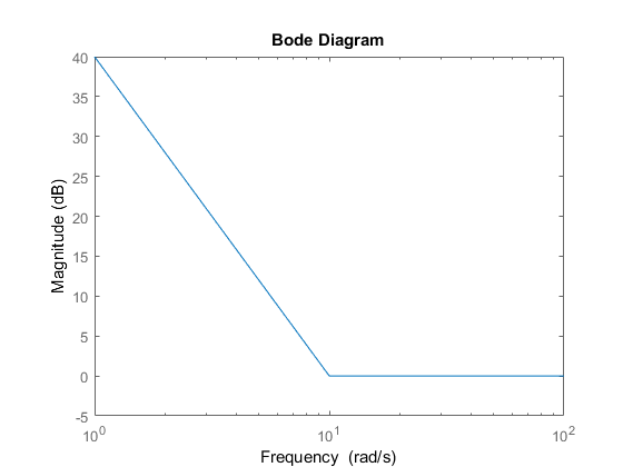
When you use an frd model to specify attfact, the
gain profile is automatically mapped onto a zpk model. The magnitude of
this zpk model approximates the desired gain profile. Use
viewGoal(Req) to visualize the resulting attenuation profile.
If you are tuning in discrete time (that is, using a genss model or
slTuner interface with nonzero Ts), you can specify
attfact as a discrete-time model with the same Ts.
If you specify attfact in continuous time, the tuning software
discretizes it. Specifying the attenuation profile in discrete time gives you more control
over the profile near the Nyquist frequency.
Properties
Examples
Constant Minimum Attenuation in Frequency Band
Create a tuning goal that enforces a attenuation of at least a factor of 10 between 0 and
5 rad/s. The tuning goal applies to a disturbance entering a control system at a point
identified as 'u'.
Req = TuningGoal.Rejection('u',10);
Req.Name = 'Rejection spec';
Req.Focus = [0 5]
Frequency-Dependent Attenuation Profile
Create a tuning goal that enforces an attenuation factor of at least 100 (40 dB) below 1 rad/s, gradually dropping to 1 (0 dB) past 10 rad/s. The tuning goal applies to a disturbance entering a control system at a point identified as 'u'.
attfact = frd([100 100 1 1],[0 1 10 100]);
Req = TuningGoal.Rejection('u',attfact);
These commands use a frd model to specify the minimum attenuation profile as a function of frequency. The minimum attenuation of 100 below 1 rad/s, together with the minimum attenuation of 1 at the frequencies of 10 and 100 rad/s, specifies the desired rolloff.
attfact is converted into a smooth function of frequency that approximates the piecewise specified profile. Display the gain profile using viewGoal.
viewGoal(Req)
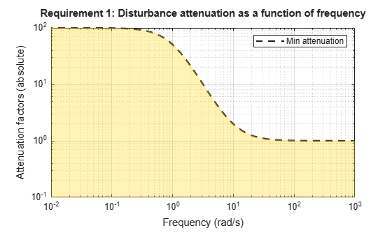
The shaded region indicates where the tuning goal is violated.
Tips
This tuning goal imposes an implicit stability constraint on the closed-loop sensitivity function measured at
Location, evaluated with loops opened at the points identified inOpenings. The dynamics affected by this implicit constraint are the stabilized dynamics for this tuning goal. TheMinDecayandMaxRadiusoptions ofsystuneOptionscontrol the bounds on these implicitly constrained dynamics. If the optimization fails to meet the default bounds, or if the default bounds conflict with other requirements, usesystuneOptionsto change these defaults.
Algorithms
When you tune a control system using a TuningGoal, the software converts
the tuning goal into a normalized scalar value f(x). In
this case, x is the vector of free (tunable) parameters in the control system.
The parameter values are adjusted automatically to minimize
f(x) or drive f(x)
below 1 if the tuning goal is a hard constraint.
For TuningGoal.Rejection, f(x) is
given by:
or its discrete-time equivalent. Here,
S(jω,x) is the closed-loop sensitivity
function measured at the disturbance location. Ω is the frequency interval over which the tuning
goal is enforced, specified in the Focus property.
WS is a frequency weighting function derived from the
specified attenuation profile. The gains of WS and
MinAttenuation roughly match for gain values ranging from –20 dB to 60 dB.
For numerical reasons, the weighting function levels off outside this range, unless the specified
attenuation profile changes slope outside this range. This adjustment is called
regularization. Because poles of
WS close to s = 0 or
s = Inf might lead to poor numeric conditioning of the
systune optimization problem, it is not recommended to specify attenuation
profiles with very low-frequency or very high-frequency dynamics.
To obtain WS, use:
WS = getWeight(Req,Ts)
where Req is the tuning goal, and Ts is the sample
time at which you are tuning (Ts = 0 for continuous time). For more
information about regularization and its effects, see Visualize Tuning Goals.
Version History
Introduced in R2016aSee Also
looptune | viewGoal | systune | systune (for slTuner) (Simulink Control Design) | looptune (for slTuner) (Simulink Control Design) | TuningGoal.Tracking | TuningGoal.LoopShape | slTuner (Simulink Control Design)
You can also select a web site from the following list:
Americas
- América Latina (Español)
- Canada (English)
- United States (English)
Europe
- Belgium (English)
- Denmark (English)
- Deutschland (Deutsch)
- España (Español)
- Finland (English)
- France (Français)
- Ireland (English)
- Italia (Italiano)
- Luxembourg (English)
- Netherlands (English)
- Norway (English)
- Österreich (Deutsch)
- Portugal (English)
- Sweden (English)
- Switzerland
- United Kingdom (English)