Generate Black Box Interface for Subsystems
R2026bYou can generate a black box interface to connect a Subsystem block to existing user-written HDL code, third-party IP, or other HDL code generated by HDL Coder™. The generated interface includes only the HDL port definitions for the subsystem, which means you can integrate external HDL code without generating implementation code for that subsystem from the model.
Use black box interfaces when you want to preserve an existing HDL implementation and connect it to the generated design under test (DUT) code by using a generated VHDL® component or Verilog® or SystemVerilog module interface. To keep custom HDL code in the model, place the code in a DocBlock block inside the black box subsystem. For more information, see Integrate Custom HDL Code by Using DocBlock.
You can use black boxes only for Subsystem blocks inside the DUT, including Virtual Subsystem and Atomic Subsystem blocks from custom libraries. By default, the generated interface includes clock, clock enable, and reset ports in addition to the subsystem input and output ports.
Generate a Black Box Interface for Subsystem
This example shows how to generate a black box interface for a subsystem and customize VHDL generics in HDL Coder.
Use this workflow when you want HDL Coder to generate only the interface for a subsystem and include that interface in the generated device under test (DUT) code. In this example, the subsystem top in the ex_blackbox_subsys model is the DUT, and the black box interface is generated for the Interface subsystem.
Open the Model
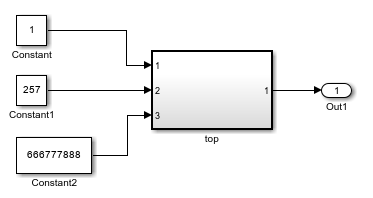
Open the ex_blackbox_subsys model, and then open the top subsystem. The top subsystem contains two lower-level subsystems, including the Interface subsystem used for black box interface generation.
load_system("ex_blackbox_subsys.slx")
open_system("ex_blackbox_subsys.slx")
open_system("ex_blackbox_subsys/top")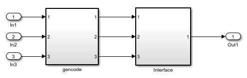
Configure the Black Box Interface
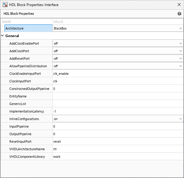
Configure the Interface subsystem to use black box implementation. Right-click the Interface subsystem. If HDL Coder options do not appear in the context menu, point to Select Apps and click HDL Coder. Then, in the HDL Coder app section, select HDL Block Properties.
Set Architecture to BlackBox. For more information on how to customize the available parameters for the black box implementation, see Customize Black Box or HDL Cosimulation Interface.
Customize VHDL Generics for the Black Box Interface
To generate VHDL generics and a generic map for a subsystem with a black box interface, set the GenericList parameter in the HDL block properties. The GenericList parameter is a cell array that contains one entry for each VHDL generic. Each entry specifies the generic name, value, and, optionally, data type.
Enter this value for the GenericList parameter:
{{'Param1','234'},{'Param2','"1"','STD_LOGIC'},{'Param3','"1101"','STD_LOGIC_VECTOR(3 DOWNTO 0)'}}
Here, Param1 is an integer, Param2 is a STD_LOGIC, and Param3 is a STD_LOGIC_VECTOR. Use double quotes for scalar and vector literal values.
You can also set the GenericList parameter programmatically by using the hdlset_param function. In the MATLAB Command Window, enter:
hdlset_param('ex_blackbox_subsys/top/Interface','GenericList',...
'{{''Param1'',''234''},{''Param2'',''"1"'',''STD_LOGIC''},{''Param3'',''"1101"'',''STD_LOGIC_VECTOR(3 DOWNTO 0)''}}');
After you set GenericList, HDL Coder includes the specified generics in the generated component declaration and GENERIC MAP for the black box interface. For more information about supported syntax and interface customization options, see Customize Black Box or HDL Cosimulation Interface.
Generate Code for Black Box Subsystem Implementation
To generate HDL code for the DUT in the ex_blackbox_subsys model, enter:
makehdl("ex_blackbox_subsys/top")### Working on the model ex_blackbox_subsys ### Generating HDL for ex_blackbox_subsys/top ### Using the config set for model ex_blackbox_subsys for HDL code generation parameters. ### Running HDL checks on the model 'ex_blackbox_subsys'. ### Begin compilation of the model 'ex_blackbox_subsys'... ### Working on the model 'ex_blackbox_subsys'... ### Working on... GenerateModel ### Begin model generation 'gm_ex_blackbox_subsys'... ### Rendering DUT with optimization related changes (IO, Area, Pipelining)... ### Model generation complete. ### Generated model saved at hdlsrc/ex_blackbox_subsys/gm_ex_blackbox_subsys.slx ### Begin VHDL Code Generation for 'ex_blackbox_subsys'. ### Working on ex_blackbox_subsys/top/gencode as hdlsrc/ex_blackbox_subsys/gencode.vhd. ### Working on ex_blackbox_subsys/top as hdlsrc/ex_blackbox_subsys/top.vhd. ### Code Generation for 'ex_blackbox_subsys' completed. ### Generating HTML files for code generation report at index.html ### Creating HDL Code Generation Check Report top_report.html ### HDL check for 'ex_blackbox_subsys' complete with 0 errors, 1 warnings, and 0 messages. ### HDL code generation complete.
HDL Coder generates HDL code for the DUT and writes the black box interface for the Interface subsystem to the generated top-level file. The gencode subsystem generates a separate file, gencode.vhd, for its VHDL entity definition. The Interface subsystem does not generate a separate file. HDL Coder writes component declaration and instantiation for the black box to top.vhd.
If you set the GenericList parameter, HDL Coder includes the specified generic in the generated component declaration and GENERIC MAP. By default, the generated interface also includes clock, clock enable, and reset ports. The generated code for the Interface subsystem includes a component definition and component instantiation as shown in the code.
  COMPONENT Interface
    GENERIC( Param1                         : integer;
             Param2                         : STD_LOGIC;
             Param3                         : STD_LOGIC_VECTOR(3 DOWNTO 0)
             );
    PORT( clk                             :   IN    std_logic;
          clk_enable                      :   IN    std_logic;
          reset                           :   IN    std_logic;
          In1                             :   IN    std_logic_vector(7 DOWNTO 0);  -- uint8
          In2                             :   IN    std_logic_vector(15 DOWNTO 0);  -- uint16
          In3                             :   IN    std_logic_vector(31 DOWNTO 0);  -- uint32
          Out1                            :   OUT   std_logic_vector(31 DOWNTO 0)  -- uint32
          );
  END COMPONENT;
  ...
 u_Interface : Interface
  GENERIC MAP( Param1 => 234,
               Param2 => "1",
               Param3 => "1101"
                 )
  PORT MAP( clk => clk,
            clk_enable => enb_const_rate,
            reset => reset,
            In1 => gencode_out1,  -- uint8
            In2 => gencode_out2,  -- uint16
            In3 => gencode_out3,  -- uint32
            Out1 => Interface_out1  -- uint32
            );

  enb_const_rate <= clk_enable;

  Out1 <= Interface_out1;
For additional customization options, including renaming or suppressing the default clock, clock enable, and reset ports, see Customize Black Box or HDL Cosimulation Interface.
Limitations
You cannot use bidirectional ports for black box interfaces.
If you place a black box subsystem that contains a DocBlock block inside another black box subsystem, HDL Coder does not integrate the HDL code from the DocBlock block during code generation.
If a black box subsystem contains a DocBlock block with custom package declarations, HDL Coder does not include those package data types in the generated interface code.
HDL Coder generates reset logic for a black box when the subsystem requires a reset signal, even if you select the MinimizeGlobalResets parameter.
You cannot perform delay balancing when you set the ImplementationLatency block property of a black box interface to a negative value.
You cannot use clock-rate pipelining for Subsystem blocks or Model blocks when you use black box interfaces.
If a subsystem is a black box interface, you cannot use Bus Element ports for masked subsystems.

