FPGA Data Capture
R2026bUse FPGA data capture to observe signals from your design while the design is running on the FPGA. This feature captures a window of signal data from the FPGA and returns the data to MATLAB® or Simulink®. To capture the signals, HDL Coder™ generates an IP core that you must integrate into your HDL project and deploy to the FPGA along with the rest of your design. HDL Coder also generates a tool, System object™, and Simulink model that communicate with the FPGA and return the data to MATLAB or Simulink.
To capture FPGA data:
Generate customized components and an IP core. Specify port names and sizes for the generated IP. These ports connect to the signals you want to capture, and the signals you want to use as triggers to control when the capture occurs.
Integrate the generated IP into your FPGA design and deploy the design to your FPGA board.
Use the generated tool, System object, or Simulink model to capture data for analysis, verification, or display. You can configure a trigger condition to control when the capture occurs and a capture condition to control which data to capture.
For this step, you must download a required hardware support package. Available support packages are:
HDL Coder Support Package for Intel® FPGA and SoC Devices
SoC Blockset™ Support Package for AMD FPGA and SoC Devices

Tools
| FPGA Data Capture Component Generator | Configure and generate FPGA data capture components |
| FPGA Data Capture | Capture data from live FPGA into MATLAB workspace interactively |
Functions
hdlverifier.FPGADataReader | Capture data from live FPGA into MATLAB workspace |
generateFPGADataCaptureIP | Open FPGA Data Capture Component Generator |
Apps
| Logic Analyzer | Visualize, measure, and analyze transitions and states over time |
Blocks
 | FPGA Data Reader | Capture data from live FPGA into Simulink model |
Topics
Overview
- Data Capture Workflow
Capture signal data from a design running on an FPGA. - Capture Asynchronous Data
Capture asynchronous data from a design running on an FPGA using multiple data capture IPs.
Data Capture Requirements and Preparation
- Set Up FPGA Design Software Tools
Set the MATLAB path to AMD®, Microchip, and Intel software. - Configure Logic Analyzer
Adjust settings in the Logic Analyzer.
Data Capture Processes
- Capture Data over PS Ethernet
Capture data over PS Ethernet interface. - Capture Data over USB Ethernet
Capture data over USB Ethernet interface. - Triggers
Use trigger conditions to capture data around specific events on the FPGA. - Capture Conditions
Use capture condition to control which data to capture from the FPGA. - Design Considerations for Data Capture
Signal, timing, and interface limitations for FPGA data capture.
Featured Examples
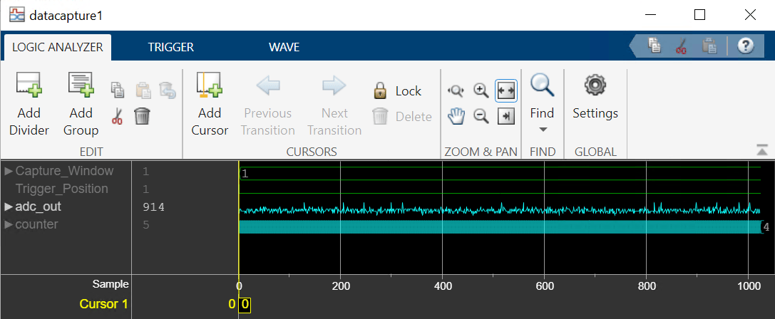
Capture Audio Signal from Intel FPGA Board Using FPGA Data Capture
Use FPGA data capture with existing HDL code to read FPGA internal signals.
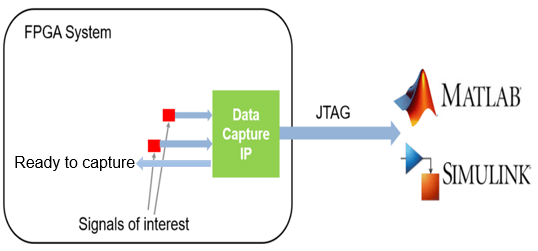
Stream Audio Signal from Intel FPGA Board Using Ready-to-Capture Signal
Use a ready-to-capture signal in FPGA data capture with existing HDL code to read FPGA streaming signals.

