Hydrostatic CVT
This example shows how to model, parameterize, and test a hydrostatic continuously variable transmission (CVT) with a swash angle shift command. When you run the plot function, it generates a comparison plot between the engine and the achieved rotational velocity in the hydraulic axial piston motor with respect to the time. Construction and agricultural equipment manufacturers use these transmissions.
Model
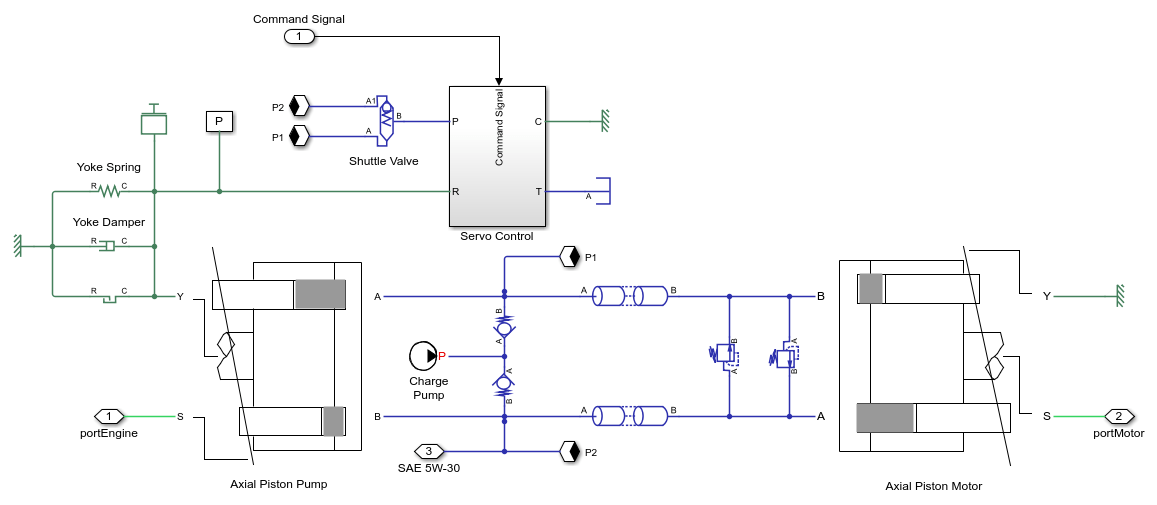
The following figure shows the model of a hydrostatic CVT. Here, connection portEngine is a physical signal port associated with the velocity source representing the engine. Connection portMotor is a physical signal port associated with the axial piston motor. Connection SAE 5W-30 is a physical signal port associated with the fluids properties of the hydraulic network. Connection Command Signal is a Simulink® input port associated with the axial piston pump swash plate angle displacement command. Driver provides the swash displacement command through speed pedal.

Hydrostatic CVT Subsystem
This subsystem demonstrates how to model and integrate the components of the hydrostatic CVT. It includes the axial piston pump, the axial piston motor, the servo control subsystem, the charge pump, the check valves, the pressure relief valves, the shuttle valve, the connection pipes and the spring, mass and damper of the servo cylinder. The charge pump maintains the pressure in the lower pressure hydraulic line between the motor and the pump at 20 bar. The charge pump required pressure is determined based on the hydraulic actuation application. The check valves connect the charge pump to the minimum pressure hydraulic line between the motor and the pump. The relief valves connect the high pressure hydraulic line to the low pressure hydraulic line between the motor and the pump. The output speed of the motor depends on the displacement of the pump, the pump input rotational speed, the leakages in the hydraulic network, and the displacement of the motor. The direction of the motor movement depends on the pump's swash angle sign. The motor rotates in positive/ forward direction for positive swash angle and rotates in the negative/reverse direction for negative swash angle of the pump.
Axial Piston Pump Subsystem
This subsystem demonstrates how to model the axial piston pump. The hydraulic pump provides hydraulic power to the motor. The subsystem includes the pump inertia, the piston subsystems, the porting volume and the cross port leakage.

Axial Piston Motor Subsystem
This subsystem demonstrates how to model the axial piston motor. The hydraulic motor converts the hydraulic power to the mechanical power. The subsystem includes the motor inertia, the piston subsystems, the porting volume and the cross port leakage.

Servo Control Subsystem
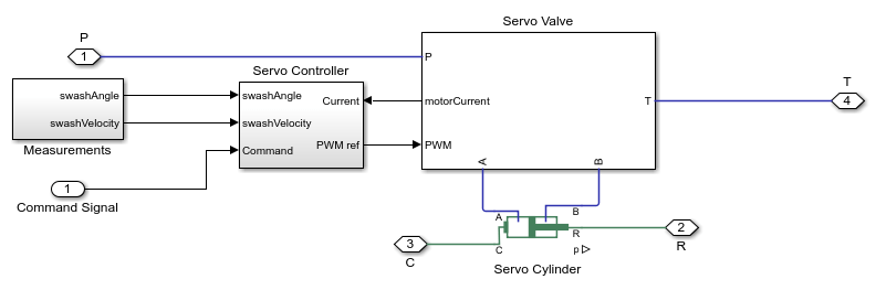
This subsystem demonstrates how to model the servo cylinder controller. It includes the measurements, the servo controller, the servo valve subsystem, and the servo cylinder. The measurements subsystem computes the swash plate angle and the swash plate velocity. The servo controller subsystem models the closed loop cascade controller for the servo valve. The cascade control has three control loops. The inner loop controls the motor current, the middle loop controls the actuator velocity, and the outer loop controls the swash plate angle. The servo valve subsystem models a two stage flapper nozzle servo valve. The servo valve actuates the servo cylinder to control the swash angle of the axial piston pump.
Simulation Results from Simscape Logging
This model generates a comparison plot between the engine and the achieved velocity in the hydraulic motor with respect to the time. The system can achieve infinite gear ratios in the forward and reverse mode.
