Configure and Simulate Non-Isolated DC-DC Converter Controller
R2026bIn this step of the Non-Isolated DC-DC Converter Controller Design Workflow example, you configure the plant model and controller gains for simulation. To get started, open the project and click the Configure and Simulate shortcut on the project toolstrip. The shortcut opens this live script so you can step through it top to bottom.
In this stage you build the Simscape™ Electrical™ plant subsystem for a Buck, Boost, or
Buck-Boost topology, configure the voltage controller subsystem reference with default or
custom proportional-integral (PI) or Type-2 compensator gains, and validate the closed-loop
response in simulation. The gains produced here are written to the topology-specific
CtrlData.mat file and are the starting point that every downstream stage
of the project (frequency response estimation (FRE) tuning, stability and sensitivity
analysis, hardware FRE, and algorithm export) consumes.
Workflow
This project guides steps to implement a Voltage Mode Controller to achieve DCDC conversion for any custom Nonisolated DC-DC converter parameters.

As shown in the diagram, this project assist to build model components including plant model (electrical circuit of converter), controller and default control parameters to start a closed-loop simulation. Workflow further extends to export the algorithm using C code generation. For advance control gain estimation or analysis, workflow demonstrates the frequency sweep across the operating frequencies both in simulation and in hardware demo.
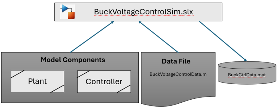
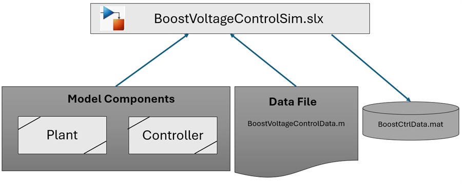
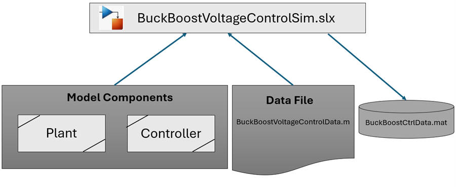
Each steps in the workflow is architect with sub-system reference for models and mat-file for data to carry forward the inputs or modifications in the previous workflow steps.
Note:
This project demonstrates all steps for Buck converter. For other type converters only simulation models are provided.
Buck converter
Model the Converter Plant
Buck converter electrical circuit is implemented as plant model using Simscape Electrical which takes the parameters from the BuckVoltageControlData.m file in "NonIsoDCDCConv = getNonIsoDCDCConvParam('Buck20W');"
"getNonIsoDCDCConvParam.m", contains the default converter parameters. For custom parameters, add your data in the switch-case.
edit getNonIsoDCDCConvParam; % Skip this section to proceed further with the default data.
In BuckVoltageControlData.m, update the below line with your custom converter name.
"NonIsoDCDCConv = getNonIsoDCDCConvParam('Buck20W');"
Converter plant model is implemented as a subsystem reference and any changes impacts the closed-loop simulation model BuckVoltageControlSim.
Note:
The converter parameters defined here is used in further workflow steps which includes closed-loop simulation, estimating the default control gains, stability analysis, Frequency response analysis.
Model the Converter Controller
This steps provide voltage controller for the converter with default control parameter tuned for the converter parameters selected in the previous step.
The subsystem reference model at ~\ModelComponents\Controller\BuckVoltageController.slx implements the voltage controller for Nonisolated DC-DC converter.
The subsystem reference model Implements controller using either default parameters or custom controller parameters. Use "GainsSelector" to choose select either default parameters or custom controller parameters.
Default Controller Parameters
For default controller gain calculation "DCDC Controller Parameters" block, uses the converter parameters defined in the previous section, and the controller sample time. The "BuckVoltageControlSim.slx" model saves default gains to 'BuckCtrlData.mat', at the end of the simulation.
Note: To change controller type the block mask parameter "Controller Type" needs to be updated in "BuckCalcCtrlParams.slx". For Type2 Compensator the default controller parameter may give very sluggish response, hence use custom parameters to enhance the response.
Custom Controller Parameters
For custom controller parameters "DCDC Controller Parameters" block uses the data stored at 'BuckCtrlData.mat'.
Use below code to update the custom controller parameters and save the data to the file "BuckCtrlData.mat".
prjPath = matlab.project.rootProject().RootFolder;
matFile = fullfile(prjPath, 'Data', 'BuckCtrlData.mat');
load(matFile); % Loads the structure BuckCtrlData
BuckCtrlData.Custom.Kp = 0.1; % Kp for PI Control
BuckCtrlData.Custom.KiTs = 0.001; % Ki*Ts for PI Control
BuckCtrlData.Custom.KTs = 0.001; % K*Ts for type2 compensators
BuckCtrlData.Custom.T1 =  0.015;%  T1 for type2 compensators
BuckCtrlData.Custom.T2 = 1e-05; % T2 for type2 compensators
BuckCtrlData.Custom.CtrlType = 1; % 1 for PI 2 for type2 compensators
% Ensure correct value of the block mask parameter "Controller Type" is selected in BuckCustomCtrlParams.slx
BuckCtrlData.Custom.timestamp =  datetime;
save(matFile, 'BuckCtrlData');
Note: Default control parameters calculated from the converter parameters or custom control parameters is used for simulation, stability analysis.
For advance control parameters estimation, use the FRD object results from Online FRE from Simulation or FRE from hardware testing as demonstrated in the section On-line FRE (Simulation) Workflow and HW FRE Workflow respectively.
Simulate the Model
Open the simulation model to simulate open-loop and closed-loop response of Buck converter. The simulation model uses the data file and subsystem reference models ("VoltageController" and "Buck"). "VoltageController" contains the blocks "DCDC Controller Parameters" and "DCDC Voltage Controller".
open_system('BuckVoltageControlSim.slx');Simulate model and run following script to save controller parameters.
saveBuckCtrlData;
Saved Controller default values to "BuckCtrlData.mat"
Open-loop simulation is used to validate the plant model and converter electrical design.
In closed-loop simulation, validate the voltage controller design, control parameters and control-loop time.
The above model is for generic Buck converter plant.
Following code are for the hardware C2000 F28378d launch pad and BOOSTXL-BUCKCONV.
open_system('BuckVoltageControlF28379d.slx');Simulate voltage mode control of plant equivalent to Buck circuit in BOOSTXL-BUCKCONV. In this model there are three option for controller parameters input which can be selected using following script file.
edit BuckVoltageControlF28379dData;Update GainsSelector variable in above file to select which controller parameters to use for voltage mode control.
For advance control parameter tuning, proceed with Simulink online FRE steps.
Tune the Controller and Sensitivity Analysis
The default controller gains are computed from the analytically derived transfer function (output to control) of the converter plant. However, this approach has limited ability to capture the true frequency response of the plant. For a more accurate characterization, the Frequency Response Estimation (FRE) workflow can be used. The FRE results can then be used to tune the controller for practical operating conditions. The online FRE workflow provided in this section uses simulation-based estimation.
The Stability Margins and Sensitivity Analysis section reports stability metrics such as gain margin, phase margin, and crossover frequency, along with their variation under different operating conditions — including output voltage variation, component parameter variation, and input voltage variation.
On-line FRE (Simulation) Workflow
Use the below live code to perform the FRE workflow on the simulation.
% On-line FRE(Simulation) Workflow
open BuckOnlineFRE.m
Stability Margins and Sensitivity Analysis
The sensitivity analysis gives out the key metrics of robustness, performance and margins of the designed controller
% Margins, Stability and sensitivity
open BuckSensitivityAnalysis.m
Hardware Deployment
HW FRE Workflow
The HW FRE workflow is based on C2000 F28378d launch pad and BOOSTXL-BUCKCONV.
open BuckC2000FREWorkflow.mC2000 Example
The hardware deployment is based on C2000 F28378d launch pad and BOOSTXL-BUCKCONV. Following model simulates voltage mode control of plant equivalent to Buck circuit in BOOSTXL-BUCKCONV and code generation to be deployed to F28378d launch pad.
open_system('BuckVoltageControlF28379d');Once code is deployed the host model can be used to enable controller and monitor signals.
Algorithm Export Workflow
This section provides the algorithm export workflow for the Nonisolated DC-DC converter controller for deploying to custom target hardware.
The workflow has two steps.
Prepare the controller parameters.
Generate C code for Voltage controller.
Prepare controller parameters
Simulate the model to compute the voltage controller parameters to be used with the converter voltage controller.
load_system('BuckCalcCtrlParamsAlgoEx');
SimOutCtrlParams = sim('BuckCalcCtrlParamsAlgoEx');
close_system('BuckCalcCtrlParamsAlgoEx');
Load computed controller parameters in the previous steps to simulink.parameter such that these values can be generated as global variables in separate C files.
LoadSimulinkParameters;
Generate C code
This section generates C code for Buck converter voltage controller. The model is configured to generate an initialize function and a step function.
The controller parameters and controller limits are generated as separate C files.
load_system('ControllerAlgoEx');
slbuild('ControllerAlgoEx');
### Searching for referenced models in model 'ControllerAlgoEx'.
### Unable to find Simulink cache file "ControllerAlgoEx.slxc".
### Total of 1 models to build.
### Starting top model code generation target build for: ControllerAlgoEx
### Build reason: "ControllerAlgoEx.c" did not exist.
### Build folder for generated code: C:\Users\kmistry\OneDrive - MathWorks\My Folders\MCB Team Work\GeckoWork\NonIsoWorkflowUpdate\buckboostworkflow\work\ControllerAlgoEx_ert_rtw
### Invoking Target Language Compiler on ControllerAlgoEx.rtw
### Using System Target File: F:\38\kmistry.Bdoc26b.j3348710\runnable\matlab\rtw\c\ert\ert.tlc
### Loading TLC function libraries
........
### Generating TLC interface API for custom data
.......
### Initial pass through model to cache user defined code
.
### Caching model source code
......................................................................
### Writing header file ControllerAlgoEx_types.h
### Writing header file ControllerAlgoEx.h
.
### Writing source file ControllerAlgoEx.c
### Writing header file ControllerAlgoEx_private.h
### Writing source file CtrlParams.c
### Writing header file CtrlParams.h
.
### Writing source file CtrlLimits.c
### Writing header file CtrlLimits.h
### Writing source file ert_main.c
### TLC code generation complete (took 8.399s).
..### Creating HTML report file index.html
### Saving binary information cache.
### Using toolchain: MinGW64 | gmake (64-bit Windows)
### Creating 'C:\Users\kmistry\OneDrive - MathWorks\My Folders\MCB Team Work\GeckoWork\NonIsoWorkflowUpdate\buckboostworkflow\work\ControllerAlgoEx_ert_rtw\ControllerAlgoEx.mk' ...
### Successful completion of code generation for: ControllerAlgoEx
### Simulink cache artifacts for 'ControllerAlgoEx' were created in 'C:\Users\kmistry\OneDrive - MathWorks\My Folders\MCB Team Work\GeckoWork\NonIsoWorkflowUpdate\buckboostworkflow\work\ControllerAlgoEx.slxc'.

Build Summary

Top model targets:

Model             Build Reason                                Status           Build Duration
=============================================================================================
ControllerAlgoEx  Target (ControllerAlgoEx.c) did not exist.  Code generated.  0h 0m 28.894s

1 of 1 models built (0 models already up to date)
Build duration: 0h 0m 35.248s
Boost converter
Model the Converter Plant
Boost converter electrical circuit is implemented as plant model using Simscape Electrical which takes the parameters from the BoostVoltageControlData.m file in "NonIsoDCDCConv = getNonIsoDCDCConvParam('Boost20W');"
"getNonIsoDCDCConvParam.m", contains the default converter parameters. For custom parameters, add your data in the switch-case.
edit getNonIsoDCDCConvParam; % Skip this section to proceed further with the default data.
In BoostVoltageControlData.m, update the below line with your custom converter name.
"NonIsoDCDCConv = getNonIsoDCDCConvParam('Boost20W');"
Converter plant model is implemented as a subsystem reference and any changes impacts the closed-loop simulation model BoostVoltageControlSim.
Model the Converter Controller
This steps provide voltage controller for the converter with default control parameter tuned for the converter parameters selected in the previous step.
The subsystem reference model at ~\ModelComponents\Controller\BoostVoltageController.slx implements the voltage controller for Nonisolated DC-DC converter.
The subsystem reference model Implements controller using either default parameters or custom controller parameters. Use "GainsSelector" to choose select either default parameters or custom controller parameters.
Default Controller Parameters
For default controller gain calculation "DCDC Controller Parameters" block, uses the converter parameters defined in the previous section, and the controller sample time. The "BoostVoltageControlSim.slx" model saves default gains to 'BoostCtrlData.mat', at the end of the simulation.
Custom Controller Parameters
For custom controller parameters "DCDC Controller Parameters" block uses the data stored at 'BoostCtrlData.mat'.
Use below code to update the custom controller parameters and save the data to the file "BoostCtrlData.mat".
prjPath = matlab.project.rootProject().RootFolder;
matFile = fullfile(prjPath, 'Data', 'BoostCtrlData.mat');
load(matFile); % Loads the structure BuckCtrlData
BoostCtrlData.Custom.Kp = 0.1; % Kp for PI Control
BoostCtrlData.Custom.KiTs = 0.001; % Ki*Ts for PI Control
BoostCtrlData.Custom.KTs = 0.001; % K*Ts for type2 compensators
BoostCtrlData.Custom.T1 =  0.015;%  T1 for type2 compensators
BoostCtrlData.Custom.T2 = 1e-05; % T2 for type2 compensators
BoostCtrlData.Custom.CtrlType = 1; % 1 for PI 2 for type2 compensators
BoostCtrlData.Custom.timestamp =  datetime;
save(matFile, 'BoostCtrlData');
Note: Default control parameters calculated from the converter parameters or custom control parameters is used for simulation.
Simulate the Model
Open the simulation model to simulate open-loop and closed-loop response of Boost converter. The simulation model uses the data file and subsystem reference models ("VoltageController" and "Boost"). "VoltageController" contains the blocks "DCDC Controller Parameters" and "DCDC Voltage Controller".
open_system('BoostVoltageControlSim.slx');Simulate model and run following script to save controller parameters.
saveBoostCtrlData;
Open-loop simulation is used to validate the plant model and converter electrical design.
In closed-loop simulation, validate the voltage controller design, control parameters and control-loop time.
Buck-Boost converter
Model the Converter Plant
Buck-Boost converter electrical circuit is implemented as plant model using Simscape Electrical which takes the parameters from the BuckBoostVoltageControlData.m file in "NonIsoDCDCConv = getNonIsoDCDCConvParam('BuckBoost20W');"
"getNonIsoDCDCConvParam.m", contains the default converter parameters. For custom parameters, add your data in the switch-case.
edit getNonIsoDCDCConvParam; % Skip this section to proceed further with the default data.
In BuckBoostVoltageControlData.m, update the below line with your custom converter name.
"NonIsoDCDCConv = getNonIsoDCDCConvParam('BuckBoost20W');"
Converter plant model is implemented as a subsystem reference and any changes impacts the closed-loop simulation model BuckBoostVoltageControlSim.
Model the Converter Controller
This steps provide voltage controller for the converter with default control parameter tuned for the converter parameters selected in the previous step.
The subsystem reference model at ~\ModelComponents\Controller\BuckBoostVoltageController.slx implements the voltage controller for Nonisolated DC-DC converter.
The subsystem reference model Implements controller using either default parameters or custom controller parameters. Use "GainsSelector" to choose select either default parameters or custom controller parameters.
Default Controller Parameters
For default controller gain calculation "DCDC Controller Parameters" block, uses the converter parameters defined in the previous section, and the controller sample time. The "BuckBoostVoltageControlSim.slx" model saves default gains to 'BuckBoostCtrlData.mat', at the end of the simulation.
Custom Controller Parameters
For custom controller parameters "DCDC Controller Parameters" block uses the data stored at 'BuckBoostCtrlData.mat'.
Use below code to update the custom controller parameters and save the data to the file "BuckBoostCtrlData.mat".
prjPath = matlab.project.rootProject().RootFolder;
matFile = fullfile(prjPath, 'Data', 'BuckBoostCtrlData.mat');
load(matFile); % Loads the structure BuckBoostCtrlData
BuckBoostCtrlData.Custom.Kp = 0.1; % Kp for PI Control
BuckBoostCtrlData.Custom.KiTs = 0.001; % Ki*Ts for PI Control
BuckBoostCtrlData.Custom.KTs = 0.001; % K*Ts for type2 compensators
BuckBoostCtrlData.Custom.T1 =  0.015;%  T1 for type2 compensators
BuckBoostCtrlData.Custom.T2 = 1e-05; % T2 for type2 compensators
BuckBoostCtrlData.Custom.CtrlType = 1; % 1 for PI 2 for type2 compensators
BuckBoostCtrlData.Custom.timestamp =  datetime;
save(matFile, 'BuckBoostCtrlData');
Note: Default control parameters calculated from the converter parameters or custom control parameters is used for simulation.
Simulate the Model
Open the simulation model to simulate open-loop and closed-loop response of Buck-Boost converter. The simulation model uses the data file and subsystem reference models ("VoltageController" and "BuckBoost"). "VoltageController" contains the blocks "DCDC Controller Parameters" and "DCDC Voltage Controller".
open_system('BuckBoostVoltageControlSim.slx');Simulate model and run following script to save controller parameters.
saveBuckBoostCtrlData;
Open-loop simulation is used to validate the plant model and converter electrical design.
In closed-loop simulation, validate the voltage controller design, control parameters and control-loop time.

