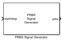
PRBS Signal Generator
Libraries:
Simulink Control Design /
Signal Generation
Description
Use this block to generate PRBS input perturbation signals. PRBS signals reduce total estimation time compared to using sinestream input signals, while producing comparable estimation results. For faster configuration, this block allows you to use the automatically generated values of the key parameters based on the specified frequencies. PRBS signals are useful for estimating frequency responses for communications and power electronics applications. For more information, see PRBS Input Signals.
This block is helpful when you to generate perturbation signals to inject in your plant models in desktop simulation or on hardware through code generation. You can then collect the plant response data to the perturbation signal and perform custom processing to identify plant characteristics.
Examples
Generate PRBS Input Signals Using PRBS Signal Generator Block
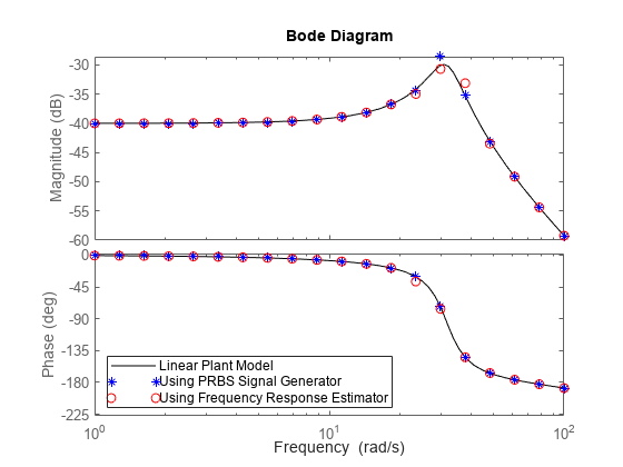
Estimate frequency responses offline using the PRBS Signal Generator block.
- Since R2024a
- Open Live Script
Use Start-Stop Generator and PRBS Signal Generator Blocks for Estimation at Multiple Operating Points
Perform frequency response estimation at multiple operating points using Start-Stop Generator and PRBS Signal Generator blocks.
- Since R2024a
- Open Live Script
Measure Boost Converter Output Impedance Using Signal Generator Blocks
Use the Sinestream Signal Generator and PRBS Signal Generator blocks to create input signals to measure the output impedance of a boost converter through an offline frequency response estimation experiment.
- Since R2024a
- Open Live Script
Ports
Input
To start and stop the estimation process, provide a signal at the
start/stop port. When the value of the signal changes
from:
Negative or zero to positive, the signal generation starts
Positive to negative or zero, the signal generation stops
Typically, you can use a signal that changes from 0 to 1 to start the experiment, and from 1 to 0 to stop it. When the experiment is not running, the block does not generate a perturbation at the output port.
Let the experiment run long enough for the algorithm to collect sufficient data for a good estimate at all frequencies it probes. The block displays a recommended experiment length in the Signal Length section of the block parameters. This value is based on the experiment mode and the frequencies you specify for the experiment.
The recommended experiment length is:
where:
Ts is the experiment sampling time, specified by the Sample time (Ts) parameter.
n is the PRBS signal order, specified by the Signal order parameter.
Np is the number of periods in the PRBS signal, specified by the Number of periods parameter.
Avoid any load disturbance to the plant during the experiment. Load disturbance can distort the plant output and reduce the accuracy of the frequency-response estimation.
Data Types: single | double
Supply a value for the Frequencies parameter. See the Frequencies parameter for information about how to choose frequencies.
When you supply frequencies via this port, specify the number of frequencies with the Number of frequencies in the excitation signal parameter.
Dependencies
To enable this port, in Excitation Signal Source, select External ports.
Data Types: single | double
Supply a value for the Amplitudes parameter. See the Amplitudes parameter for details.
Dependencies
To enable this port, in Excitation Signal Source, select External Ports.
Data Types: single | double
Output
The block generates the PRBS perturbation signal at this port.
Parameters
To edit block parameters interactively, use the Property Inspector. From the Simulink® Toolstrip, on the Simulation tab, in the Prepare gallery, select Property Inspector.
The block is a discrete-time block that runs at a fixed sample time, specified with this parameter. The largest frequency that you can estimate is the Nyquist frequency, π/Ts rad/s. Best practice is to use a sample time at least five times faster than the Nyquist frequency.
Ts = π/(5ωmax) ≅ 0.6/ωmax or 0.1/fmax,
Here, ωmax is the highest frequency in the Frequencies parameter in rad/s, and fmax is the highest frequency in Hz. The sample time must be small enough to estimate the fastest desired frequency, but not so small as to introduce unnecessary computational burden.
If you set the sample time to –1, then the software determines the sample time on compilation, based on the sources outside the block. Setting sample time to –1 disables the internal checks in the block that ensure your estimation frequencies are below the Nyquist frequency.
Tip
If you want to run the deployed block with different sample times in your application, set this parameter to –1 and put the block in a Triggered Subsystem. Then, trigger the subsystem at the desired sample time. If you do not plan to change the sample time after deployment, specify a fixed and finite sample time.
Specify the floating-point precision based on simulation environment or hardware requirements.
Specify whether to supply the frequencies and amplitudes of the experiment perturbation signal via block parameters or via external ports.
Block parameters — Select to enable the Frequencies and Amplitudes parameters.
External ports — Select to enable the w and amp input ports. Use this option if you want to change the frequencies and amplitudes of the perturbation signal after deployment.
Frequencies at which to estimate the frequency response of the plant. The block injects a perturbation at each of these frequencies. The highest frequency you can estimate is limited by the Nyquist frequency, π/Ts rad/s, where Ts is the value you set for the Sample time (Ts) parameter.
For PRBS signals, the range of frequencies affect the experiment length. The lowest frequency value determines the minimum signal order that can cover the specified frequency. Decreasing the lowest frequency range increases the minimum signal order required, therefore increasing the experiment length. However, due to wideband properties of the PRBS input signals, adding more frequency points does not increase the experiment length.
Tips
This parameter is not tunable. To provide frequencies after deployment, set Excitation Signal Source to External ports and use the w input port.
Dependencies
To enable this parameter, set Excitation Signal Source to Block parameters.
Specify the amplitudes of the perturbation signals injected into the plant. To use the same amplitude for all frequencies, specify a scalar value. If you know that the response changes significantly over range of frequencies to estimate, then you can use a vector to specify a different amplitude for each frequency. For instance, you can use a smaller value around known resonant frequencies and a larger value above the rolloff frequency. The vector must be the same length as the vector you provide for Frequencies.
The amplitudes must be:
Large enough that the perturbation overcomes any deadband in the plant actuator and generates a response above the noise level
Small enough to keep the plant running within the approximately linear region near the nominal operating point, and to avoid saturating the plant input or output
Tip
This parameter is not tunable. To provide amplitudes after deployment, set Excitation Signal Source to External ports and use the amp input port.
Dependencies
To enable this parameter, set Excitation Signal Source to Block parameters.
When you provide the experiment frequencies via the external port w, specify the number of frequencies (the length of the vector signal at w) with this parameter.
Dependencies
To enable this parameter, set Excitation Signal Source to External ports.
Number of periods in the PRBS signal, specified as a positive integer.
Based on specified frequencies and sample time, the block displays a recommended value for this parameter in the Signal Length section of the block dialog.
Signal order, specified as a positive integer. The maximum length of the PRBS signal is 2n–1, where n is the signal order. To obtain an accurate frequency response estimation, the length of the PRBS must be sufficiently large.
For a given sample time, to obtain a higher frequency resolution, specify a larger signal order. Specify a value less than or equal to 24 to prevent the experiment from running for too long.
Based on specified frequencies and sample time, the block displays a recommended value for this parameter in the Signal Length section of the block dialog.
The block calculates the recommended values for the Number of periods and Signal order parameters, based on the specified frequencies and sample time. Enable this option to use the automatically generated values for either one or both of the PRBS signal parameters. This is useful when you are running multiple experiments with changing frequency range or sample time.
Extended Capabilities
C/C++ Code Generation
Generate C and C++ code using Simulink® Coder™.
Version History
Introduced in R2024a
MATLAB Command
You clicked a link that corresponds to this MATLAB command:
Run the command by entering it in the MATLAB Command Window. Web browsers do not support MATLAB commands.
Select a Web Site
Choose a web site to get translated content where available and see local events and offers. Based on your location, we recommend that you select: .
You can also select a web site from the following list
How to Get Best Site Performance
Select the China site (in Chinese or English) for best site performance. Other MathWorks country sites are not optimized for visits from your location.
Americas
- América Latina (Español)
- Canada (English)
- United States (English)
Europe
- Belgium (English)
- Denmark (English)
- Deutschland (Deutsch)
- España (Español)
- Finland (English)
- France (Français)
- Ireland (English)
- Italia (Italiano)
- Luxembourg (English)
- Netherlands (English)
- Norway (English)
- Österreich (Deutsch)
- Portugal (English)
- Sweden (English)
- Switzerland
- United Kingdom (English)


