Apply UDP Receive Block with Messages from Multiple IP Senders
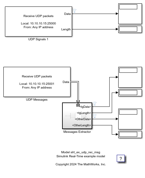
This example shows two possible ways to get the UDP data from the UDP Receive block, by using the signal (see upper signal flow in the model) or by using messages (see lower signal flow in the model). The message signal flow uses the Message Triggered Subsystem to get the message and divide the messages into two signals.
Open Model
model = 'slrt_ex_udp_rec_msg';
open_system(model);
Challenges with Signal-Based UDP Blocks
Some challenges occur when using a signal-based approach with the UDP Receive block for data from multiple IP addresses:
Data Accumulation: The socket accumulates too much data when the sender frequency is higher than the UDP Receive block sample frequency. This condition can lead to backlogs.
No IP Identification: The data is mixed from multiple source IP addresses. The model requires multiple blocks with unique ports to isolate source IP addresses.
Configuration Complexity: The model complexity increases with multiple source IP addresses. This complexity can make it hard to manage IP-specific data.
Advantages of Message-Based UDP Handling
Many of the challenges in a signal-based approach for handling data from multiple IP addresses are resolved by using a message-based approach with the UDP Receive block. The model can:
Use message-triggered subsystems to enable IP-based filtering. This filtering permits selective data routing without resorting to multiple UDP Receive blocks.
Handle packets immediately. The message-based approach lets you handle multiple packets in each time step, thus bypassing time-step delays.
Control data buffering with a Queue block. The Queue block capacity and type (LIFO/FIFO) determine how the model processes accumulated packets. See Experimenting with the Queue Block at the end of this example.
Handle multiple source IP addresses with a single UDP Receive block via message-based routing. Port and block count are reduced.
Access sender metadata. The message contains the IP address and port of the sender. You can use that information in your model logic to route data from different senders to different outputs.
UDP Packet Bus
When you configure a UDP Receive block in message mode, a UDP_Packet is automatically created to wrap the incoming data. This bus groups these fields:
data- A type uint8 field holding a fixed-size array determined by the Receive Width parameter.length- A type uint16 field holding the actual number of bytes received.IP- A type uint8 field holding the source IP address of the sender (4 bytes).IP_Port- A type uint16 field holding the source port of the sender.
This example uses only IP_Port for routing, but you can also use the IP field to filter by source address if needed.
If the incoming data exceeds the data array size, it gets truncated to fit. If it is less, the remaining bytes are filled with zeros. For more details, see UDP Receive.
View Method Comparison by Using the Simulation Data Inspector
This figure compares the signal-based and message-based approaches that the model uses to get data from the UDP Receive block. The signal-based approach (see upper signal flow in the model) data in the figure is labeled Graphic 1. The message-based approach (see lower signal flow in the model) data in the figure is labeled Graphic 2.


Model Architecture
The model has two subsystems (enable one at a time):
Signals Subsystem: A standard UDP Receive block configured in signal mode on port 25000. It outputs Data and Length directly. All incoming packets from any sender are mixed into a single output with no sender identification.
Messages Subsystem: A UDP Receive block configured in message mode on port 25000. The output goes through a Queue block and then into a Message Triggered Subsystem called Messages Extractor.
Messages Extractor Subsystem Inside the Messages Extractor, a Bus Selector extracts the IP_Port, Length, and Data fields from the UDP_Packet bus. These are passed to a MATLAB Function block (routeData) that separates the data based on the sender source port:
function [tgData, tgLength, OtherData, OtherLength] = routeData(IP_Port, Length, Data)
persistent prevOut;
if isempty(prevOut)
    prevOut = {uint8(0) uint16(0) uint8(0) uint16(0)};
end
TgPort = 25001;
if isequal(IP_Port, TgPort)
    tgData = Data;
    tgLength = Length;
    OtherData = prevOut{3};
    OtherLength = prevOut{4};
else
    tgData = prevOut{1};
    tgLength = prevOut{2};
    OtherData = Data;
    OtherLength = Length;
end
prevOut{1} = tgData;
prevOut{2} = tgLength;
prevOut{3} = OtherData;
prevOut{4} = OtherLength;
end
The function routes packets from source port 25001 to the tgData/tgLength outputs, and packets from any other source port to the OtherData/OtherLength outputs. A persistent variable retains the last known value for each output.
Host-Side Script: Send Sine and Cosine via UDP
Use the following script on the host computer can be used to send test signals to the target. Each signal is sent from a different source port so the model can distinguish them. See udp_send_sine_cosine.m.
targetIP   = '10.10.10.15';
targetPort = 25000;
u1 = udpport("IPV4", "LocalHost", "0.0.0.0", "LocalPort", 25001);
u2 = udpport("IPV4", "LocalHost", "0.0.0.0", "LocalPort", 25002);
% Signal parameters
fs       = 100;   % Sample rate (Hz)
duration = 5;     % Duration (seconds)
f        = 1;     % Signal frequency (Hz)
t = 0:1/fs:duration;
for k = 1:length(t)
    sineData = uint8((sin(2*pi*f*t(k)) + 1) * 127.5);
    write(u1, sineData, 'uint8', targetIP, targetPort);
    cosineData = uint8((cos(2*pi*f*t(k)) + 1) * 127.5);
    write(u2, cosineData, 'uint8', targetIP, targetPort);
    pause(1/fs);
end
clear u1 u2
The script sends a sine wave from source port 25001 and a cosine wave from source port 25002, both to the target on destination port 25000. The model routes the sine data to tgData and the cosine data to OtherData based on the source port.
Create Target Object and Connect
Create a Target object and connect to the default target computer.
tg = slrealtime;
connect(tg);
Configure Model
Open the example model. Configure STF selection. Configure IP address for UDP Receive blocks. Set the stop time.
modelSTF = getSTFName(tg);
set_param(model,"SystemTargetFile",modelSTF);
targetIP = '192.168.7.5';
set_param([model,'/UDP Signals 1'],'ipAddress',targetIP);
set_param([model,'/UDP Messages'],'ipAddress',targetIP);
set_param(model,'StopTime','20');
Build, Load, and Run Real-Time Application
Build the real-time app. Use evalc to suppress build messages. Load and start the real-time application. Wait while the application runs.
evalc('slbuild(model)');
load(tg,'slrt_ex_udp_rec_msg');
start(tg);
pause(25);
Close Model
bdclose(model);
clear;
Experimenting with the Queue Block
The Queue block in this example is configured as LIFO (Last-In, First-Out). You can experiment with its Capacity parameter to observe two different behaviors:
Capacity = 1000, Model base rate = 1 s: The queue stores all incoming packets. Since the host script sends faster (100 Hz) than the model consumes (1 Hz), data accumulates. The model continues outputting buffered data in the SDI even after the script finishes, drawing the full waveform over an extended period.
Capacity = 1, Model base rate = 1 s: New messages overwrite the single queued message. The model only ever sees the latest packet at each time step. The SDI output stops as soon as the script finishes, but you will not see a smooth waveform since most samples are discarded.
To try this, change the Queue block Capacity parameter and set the model base rate to 1 second. Then run the host script and compare the Simulation Data Inspector results.