EtherCAT Protocol with Beckhoff Digital IO Subordinate Devices EL1004 and EL2004
This example shows how to communicate with EtherCAT® devices using the Beckhoff® digital I/O terminals EL1004 and EL2004.
Requirements
To run this example, you need an EtherCAT network that consists of the target computer as EtherCAT Main device and two analog input/output terminals EL1004 and EL2004 as EtherCAT Subordinate devices attached to an EK1100 coupler.
EtherCAT in Simulink® Real-Time™ requires a dedicated network port on the target computer that is reserved for EtherCAT use by using the Ethernet configuration tool. Configure the dedicated port for EtherCAT communication, not with an IP address. The dedicated port must be distinct from the port used for the Ethernet link between the development and target computers.
To test this model:
Connect the port that is reserved for EtherCAT in the target computer to the network IN port of the Beckoff EK1100 coupler.
Assemble Terminals EL1004 and EL2004 with Coupler EK1100.
Loop back the first two I/O ports: Connect ports numbered O1 and O2 of Terminal EL2004 to ports numbered I1 and I2 of Terminal EL1004. Ports O3, O4, I3 and I4 are not used by this example.
Make sure that the terminals are supplied with the required 24-volt power supply.
Build and download the model onto the target.
For a complete example that configures the EtherCAT network, configures the EtherCAT main device node model, and builds then runs the real-time application, see the Simulink Real-Time EtherCAT documentation.
Open the Model
This model drives a pulse wave signal and transmits the signal and its inverse as Boolean values to the EL2004 terminal, and receives the input signal transmitted by the EL1004 terminal.
The EtherCAT initialization block can be configured with either the full path to the ENI file or with a relative path that can be found with the MATLAB which command. Copy the example configuration file from the example folder to the current folder. To open the model, in the MATLAB® Command Window, type:
open_system('slrt_ex_ethercat_beckhoff_dio');

Figure 1: EtherCAT model using Beckhoff digital I/O terminals EL1004 and EL2004.
Configure the Model
Open the parameter dialog for the EtherCAT Init block and observe the pre-configured values. The EtherCAT subordinate devices that are daisy chained together with Ethernet cable is a Device, also referred to as an EtherCAT network. The Device Index selects one such chained EtherCAT network. The Ethernet Port Number identifies which Ethernet port to use to access that Device. The EtherCAT Init block connects these two so that other EtherCAT blocks use the Device Index to communicate with the subordinate devices on that EtherCAT network.
If you only have one connected network of EtherCAT subordinate devices, and you have only reserved one Ethernet port with the Ethernet configuration tool, use Device Index = 0 and Ethernet Port Number = 1.
Describe Network with Configurator
Using a third-party EtherCAT configuration program that you install on a development computer, generate an EtherCAT configuration (ENI) file. The ENI file for this example is BeckhoffDIOconfig.xml.
The ENI (EtherCAT Network Information) file that is provided with this example has an EK1100 with EL2004 and EL1004 subordinate devices attached, in that order. If you have different digital IO modules, you need to create a new ENI file for that collection.
For an overview of the process for creating an ENI file, see Configure EtherCAT Network by Using TwinCAT 3.
Each EtherCAT configuration file (ENI file) is specific to the exact network setup from which it was created (for example, the network discovered in step 1 of the configuration file creation process). The configuration file provided for this example is valid if and only if the EtherCAT network consists of Terminals EK1100, EL1004, and EL2004 from Beckhoff.
The ENI file defines a set of transmit and receive variables. For this example, four receive variables are defined for the four input channels of Terminal EL1004. Only the first two channels of Terminal EL1004 are used in this example. Make sure the receive variables for channel 1 and channel 2 of terminal EL1004 are selected respectively in the two EtherCAT PDO Receive blocks. These two variables are Term 3 (EL1004).Channel 1.Input and Term 3 (EL1004).Channel 2.Input. In the same way, four transmit variables are defined for the four output channels of terminal EL2004, but only the first two channels are tested in this example. Make sure the transmit variables for channel 1 and channel 2 of terminal EL2004 are selected respectively in the two EtherCAT PDO Transmit blocks. These two variables are Term 2 (EL2004).Channel 1.Output and Term 2 (EL2004).Channel 2.Output.
Build, Download, and Run the Model
To build, download, and run the model:
In the Simulink Editor, from the targets list on the Real-Time tab, select the target computer on which to run the real-time application.
Click Run on Target.
If you open the three host side scopes by double clicking each, data is relayed from the target back to the development computer and displayed.
The three scopes are Scope, Scope1 and Scope2.

Both notifications from the EtherCAT state machine and the current state are displayed in Scope. Since there are no errors, the only notifications visible are the value 1 which means a state change at that execution time step. The current state indicates the state that resulted from that state change. Notice that Op (=8) state is reached very fast since this ENI file does not include distributed clock synchronization. This view is zoomed in to the first 0.2 seconds of execution to show the transition to Op state clearly.
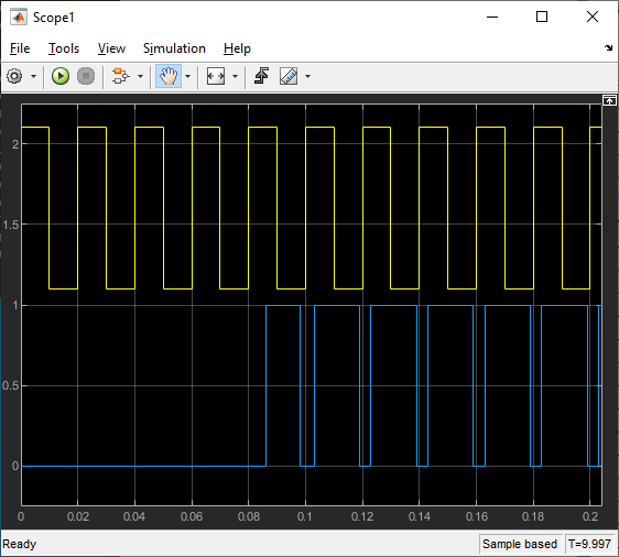

Scope1 and Scope2 show almost the same thing, but for two different channels. The signal is inverted between the two of them as can be seen if you compare the time when there is a rising edge in the yellow trace. The time step when physical IO starts is when the state goes to Op state. Before that, there is no input or output and the blue traces stay at 0. There is a time delay between the signal being sent to the output blocks and the signal that comes back from the input blocks for two reasons.
There is a 2 time step delay due to EtherCAT communication which is followed by an additional delay due to the speed of the hardware IO. The return signal shows a definite asymmetry between the delay after sending a rising edge and the delay after sending a falling edge. If you inspect the actual output signal with an oscilloscope, you see that the output is actually symmetric, but it is the input that has additional hardware delay in it. Other DIO subordinate devices show different delay characteristics.
The model is preconfigured to run for 10 seconds. If you want to run the model longer, pull down the Run on Target menu and change the number on the bottom line. Press the green arrow to configure, build, and run.
Display the Target Computer Data
After running the model, you can use the Simulation Data Inspector to view any signal that has been marked for signal logging. Signals marked for signal logging have a dot with two arcs above it in the model editor.
Observations to Notice
Because data is both received from and sent to the subordinate devices as the final action during execution and received data on one time step is only available during the following time step, you should see a delay between the data being sent and the return value. In addition with digital IO, writing a new value to an output takes a few microseconds to appear as a change in voltage which is after the input was captured, there is a 2 time step delay from an output edge until the input shows the edge in the data.
Close the Model
When the example completes its run, stop and close the model.
close_system('slrt_ex_ethercat_beckhoff_dio');
See Also
You can also select a web site from the following list:
Americas
- América Latina (Español)
- Canada (English)
- United States (English)
Europe
- Belgium (English)
- Denmark (English)
- Deutschland (Deutsch)
- España (Español)
- Finland (English)
- France (Français)
- Ireland (English)
- Italia (Italiano)
- Luxembourg (English)
- Netherlands (English)
- Norway (English)
- Österreich (Deutsch)
- Portugal (English)
- Sweden (English)
- Switzerland
- United Kingdom (English)