PI Controller (Discrete or Continuous)
R2026bDiscrete-time or continuous-time PI controller with external anti-windup input
PI Controller (Discrete or Continuous) block

To add a block to a model, double-click the canvas and start typing the block name. Then, select the block from the list.
Libraries:
Simscape /
Electrical /
Control /
General Control
Description
The Discrete PI Controller block implements discrete-time or continuous-time PI control with external anti-windup input.
This diagram shows the equivalent circuit for the controller with external anti-windup input.

Equations
The PI Controller (Discrete or Continuous) block calculates the control signal using the backward Euler discretization method:
where
u is the control signal.
Kp is the proportional gain coefficient.
Ki is the integral gain coefficient.
Kaw is the anti-windup gain coefficient.
Ts is the sampling period.
e is the error signal.
To prevent excessive overshoot, the block can use back calculation to implement an external anti-windup mechanism. It inputs du(k), the difference between the saturated control signal, usat(k), and the calculated unsaturated control signal, u(k). It then multiplies the difference by the anti-windup coefficient and adds the amplified signal from the integral gain.
Examples
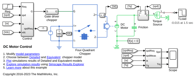
DC Motor Control
A cascade speed-control structure for a DC motor. A PWM controlled four-quadrant Chopper is used to feed the DC motor. The Control subsystem includes the outer speed-control loop, the inner current-control loop, and the PWM generation. The total simulation time (t) is 4 seconds. At t = 1.5 seconds, the load torque increases. At t = 2.5 seconds, the reference speed is changed from 1000 rpm to 2000 rpm.
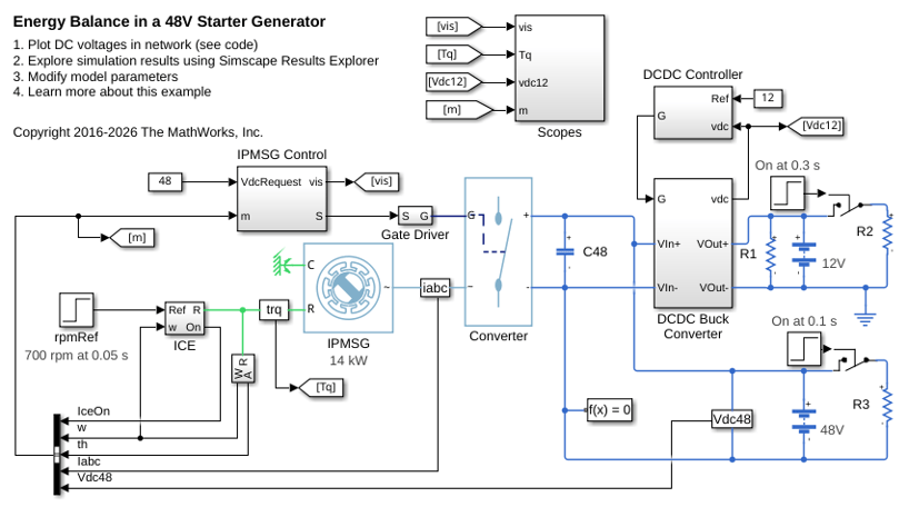
Energy Balance in a 48V Starter Generator
An interior permanent magnet synchronous machine (IPMSM) used as a starter/generator in a simplified 48V automotive system. The system contains a 48V electric network and a 12V electric network. The internal combustion engine (ICE) is represented by basic mechanical blocks. The IPMSM operates as a motor until the ICE reaches the idle speed and then it operates as a generator. The IPMSM supplies power to the 48V network, which contains the R3 power consumer. The 48V network supplies power to the 12V network which has two consumers: R1 and R2. The total simulation time (t) is 0.5 seconds. At t = 0.05 seconds, the ICE turns on. At t = 0.1 seconds, R3 switches on. At t = 0.3 seconds, R2 switches on and increases the load on the 12V electric network. The EM Controller subsystem includes a multi-rate PI-based cascade control structure which has an outer voltage-control loop and two inner current-control loops. The task scheduling in the Control subsystem is implemented as a Stateflow® state machine. The DCDC Controller subsystem implements a simple PI controller for the DC-DC Buck converter, which feeds the 12V network. The Scopes subsystem contains scopes that allow you to see the simulation results.
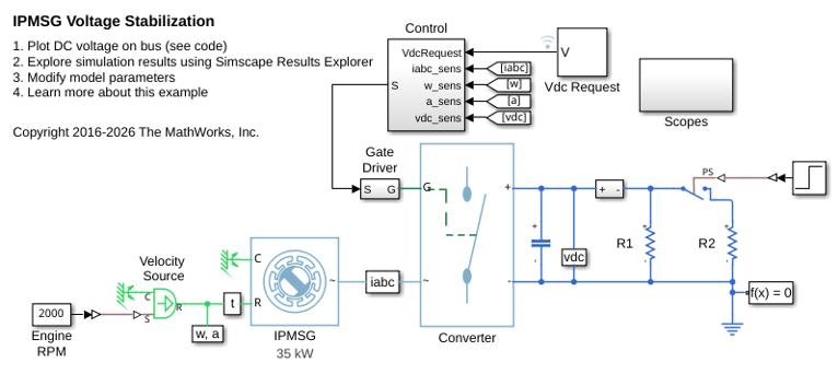
IPMSG Voltage Stabilization
Control an Interior Permanent Magnet Synchronous Generator (IPMSG) based low voltage generator system for a hybrid electric vehicle (HEV). The Control subsystem includes a multi-rate PI-based cascade control structure which has an outer voltage-control loop and two inner current-control loops. The task scheduling in the Control subsystem is implemented as a Stateflow® state machine. The Scopes subsystem contains scopes that allow you to see the simulation results. An ideal angular velocity source, which represents a combustion engine, drives the IPMSG. The IPMSG supplies low-voltage power to loads R1 and R2. At t = 0.4 seconds, the switch closes, increasing the load.
Ports
Input
Output
Parameters
References
[1] Åström, K. and T. Hägglund. Advanced PID Control. Research Triangle Park, NC: ISA, 2005.

