PWM Gate Signal Generator (Five-phase, Two-level)
Generate ten switch-controlling pulses for five-phase, two-level gating switching devices
Libraries:
Simscape /
Electrical /
Control /
Pulse Width Modulation
Description
The PWM Gate Signal Generator (Five-phase, Two-level) block controls the switching behavior for a five-phase, two-level power converter. The block uses the gating times provided as inputs to generate ten switch-controlling pulses. You can obtain the gating time information using the PWM Timing and Waveform Generator (Five-phase, Two-level) block.
Sampling Mode
This block allows you to choose natural, symmetric, or asymmetric sampling of the modulation wave.
The PWM Gate Signal Generator (Five-phase, Two-level) block does not perform carrier-based pulse width modulation (PWM). Instead, the block uses the gating times to generate both the switch-controlling pulses and the modulation waveforms that the block outputs.
Carrier-based PWM is, however, useful for showing how the sampling mode that you select relates to the switch-on and switch-off behavior of the pulses that the block generates. A generator that uses a three-level, carrier-based PWM method:
Samples a reference wave
Compares the sample to two parallel triangle carrier waves, separated by one level
Generates a switch-on pulse if a sample is higher than the carrier signal or a switch-off pulse if a sample is lower than the carrier wave
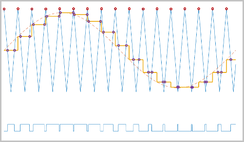
To determine switch-on and switch-off pulse behavior, a three-level carrier-based PWM generator uses these methods to sample each of the triangle waves:
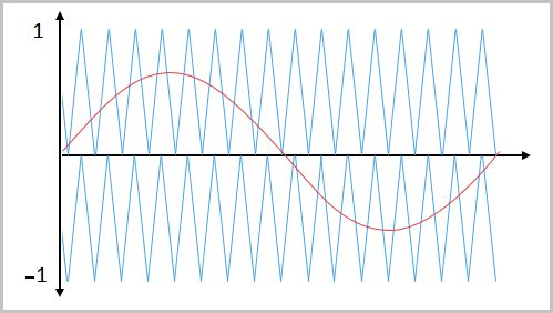
Natural — The sampling and comparison occur at the intersection points of the modulation wave and the carrier wave.
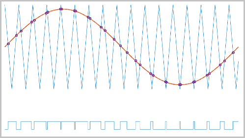
Asymmetric — Sampling occurs at the upper and lower boundaries of the carrier wave. The comparison occurs at the intersection that follows the sampling.
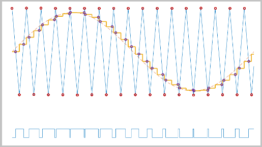
Symmetric — Sampling occurs only at the upper boundary of the carrier wave. The comparison occurs at the intersection that follows the sampling.
Ports
Input
Output
Parameters
Extended Capabilities
Version History
Introduced in R2021a