Build and Simulate a Simple DC Motor
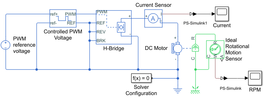
In this example, you model a DC motor driven by a constant input signal that approximates a pulse-width modulated signal and look at the current and rotational motion at the motor output.
To see the completed version of the model you create in this example, open the Control DC Motor with PWM Voltage Source and H-Bridge Driver example.
Select Blocks to Represent System Components
Select the blocks to represent the input signal, the DC motor, and the motor output displays.
The following table describes the role of the blocks that represent the system components.
Block | Description |
|---|---|
| Solver Configuration | Defines solver settings that apply to all physical modeling blocks |
| PS-Simulink Converter | Converts the input physical signal to a Simulink® signal |
| Controlled PWM Voltage | Generates the signal that approximates a pulse-width modulated motor input signal |
| H-Bridge | Drives the DC motor |
| DC Motor | Converts input electrical energy into mechanical motion |
| Current Sensor | Converts the electrical current that drives the motor into a measurable physical signal proportional to the current |
| DC Voltage Source | Generates a DC voltage |
| Electrical Reference | Provides the electrical ground |
| Mechanical Rotational Reference | Provides the mechanical ground |
| Ideal Rotational Motion Sensor | Converts the rotational motion of the motor into a measurable physical signal proportional to the motion |
| Scope | Displays motor current and rotational motion |
Build the Model
Create a new model.
Add the blocks in this table. The Library Path column specifies the hierarchical path to each block.
Block
Library Path
Quantity
Solver Configuration Simscape > Utilities
1
PS-Simulink Converter Simscape > Utilities
2
Controlled PWM Voltage Simscape > Electrical > Integrated Circuits
1
H-Bridge Simscape > Electrical > Semiconductors & Converters > Converters
1
DC Motor Simscape > Electrical > Electromechanical > Brushed Motors
1
Current Sensor Simscape > Foundation Library > Electrical > Electrical Sensors
1
DC Voltage Source Simscape > Foundation Library > Electrical > Electrical Sources
1
Electrical Reference Simscape > Foundation Library > Electrical > Electrical Elements
1
Mechanical Rotational Reference Simscape > Foundation Library > Mechanical > Rotational Elements
1
Ideal Rotational Motion Sensor Simscape > Foundation Library > Mechanical > Mechanical Sensors
1
Scope Simulink > Commonly Used Blocks
2
Note
You can use the Simscape™ function
sscnewwith domain typeelectricalto create a Simscape model that contains these blocks:Simulink-PS Converter
PS-Simulink Converter
Scope
Solver Configuration
Electrical Reference
Rename and connect the blocks as shown in the diagram.
Now you are ready to specify block parameters.
Specify Model Parameters
Specify these parameters to represent the behavior of the system components:
Model Setup Parameters
These blocks specify model information that is not specific to a particular block:
Solver Configuration
Electrical Reference
Mechanical Rotational Reference
As with Simscape models, you must include a Solver Configuration block in each topologically distinct physical network. This example has a single physical network, so use one Solver Configuration block with the default parameter values.
You must include an Electrical Reference block in each Simscape Electrical™ network. You must include a Mechanical Rotational Reference block in each network that includes electromechanical blocks. These blocks do not have any parameters.
For more information about using reference blocks, see Grounding Rules.
Motor Input Signal Parameters
You generate the motor input signal using these blocks:
The DC Voltage Source block (PWM reference voltage) generates a constant signal.
The Controlled PWM Voltage block generates a pulse-width modulated signal.
The H-Bridge block drives the motor.
In this example, all input ports of the H-Bridge block except the PWM port are connected to ground. As a result, the H-Bridge block behaves as follows:
When the motor is on, the H-Bridge block connects the motor terminals to the power supply.
When the motor is off, the H-Bridge block acts as a freewheeling diode to maintain the motor current.
In this example, you simulate the motor with a constant current whose value is the average value of the PWM signal. By using this type of signal, you set up a fast simulation that estimates the motor behavior.
In the DC Voltage Source block, set the Constant voltage parameter to
2.5V.Set the parameters of the Controlled PWM Voltage block:
PWM frequency —
4000HzSimulation mode —
AveragedThis value tells the block to generate an output signal whose value is the average value of the PWM signal. Simulating the motor with an averaged signal estimates the motor behavior in the presence of a PWM signal. To validate this approximation, use value of
PWMfor this parameter.
In the H-Bridge block, set the Simulation mode parameter to
Averaged.This value tells the block to generate an output signal whose value is the average value of the PWM signal. Simulating the motor with an averaged signal estimates the motor behavior in the presence of a PWM signal. To validate this approximation, use value of
PWMfor this parameter.
Note
The simulation mode for both the Controlled PWM Voltage and H-Bridge blocks must be the same.
Motor Parameters
Configure the block that models the motor.
Set the parameters of the DC Motor block, leaving the unit settings at their default values where applicable:
Electrical Torque section:
Model parameterization —
By
                                        rated load and speed
Armature inductance —
0.01HNo-load speed —
4000rpmRated speed (at rated load) —
2500rpmRated load (mechanical power) —
10WRated DC supply voltage —
12V
Mechanical section:
Rotor inertia —
0.0002kg*m^2Rotor damping —
0.5e-5N*m/(rad/s)
Current Display Parameters
Specify the parameters of the blocks that create the motor current display:
Current Sensor block
PS-Simulink Converter1 block
Current scope
Of the three blocks, only the PS-Simulink Converter1 block has parameters. Set the
PS-Simulink Converter1 block Output signal unit parameter to
A to indicate that the block input signal has units of
amperes.
Torque Display Parameters
Specify the parameters of the blocks that create the motor torque display:
Ideal Rotational Motion Sensor block
PS-Simulink Converter block
RPM scope
Of the three blocks, only the PS-Simulink Converter
block has parameters you need to configure for this example. Set the
PS-Simulink Converter block Output
signal unit parameter to rpm to indicate that the
block input signal has units of revolutions per minute.
Note
You must type this parameter value. It is not available in the drop-down list.
Configure the Solver Parameters
Configure the solver parameters to use a continuous-time solver. Simscape Electrical models only run with a continuous-time solver when you clear the Local Solver parameter of a Solver Configuration block. Use the Configuration Parameters dialog box to change the simulation end time, tighten the relative tolerance for a more accurate simulation, and remove the limit on the number of simulation data points Simulink saves.
In the model window, select Modeling > Model Settings to open the Configuration Parameters dialog box.
In the left pane, click Solver:
Set Stop time to
10.Set Solver to
ode15s (Stiff/NDF).Set Max step size to
1.Set Relative tolerance to
1e-3.
Click OK.
For more information about configuring solver parameters, see Simulating an Electronic, Mechatronic, or Electrical Power System.
Run the Simulation and Analyze the Results
Run the simulation and plot the results. In the model window, select Simulation > Run.
To view the motor current and torque, double-click the Scope blocks. You can do this before or after you run the simulation.
Note
By default, the scope displays appear stacked on top of each other on the screen, so you can only see one of them. Click and drag the windows to reposition them.
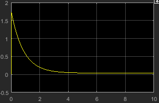
This figure shows the motor current.
This figure shows the motor rpm.
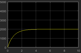
As expected, the motor runs at about 2000 rpm when the applied DC voltage is 2.5 V.
See Also
Controlled PWM Voltage | DC Motor | H-Bridge
Topics
- Control DC Motor with PWM Voltage Source and H-Bridge Driver
- Design PID Control for DC Motor Using Classical Control Theory
- Simulating an Electronic, Mechatronic, or Electrical Power System
- Build and Simulate a Simple Circuit
- Build and Simulate Single-Phase Half-Bridge Inverter with Ideal Switches and Thermal Port