Communicate with SPI-Based EEPROM Using Arduino Hardware
This example shows how to use Simulink® Support Package for Arduino® Hardware to enable and write to/read from an SPI based EEPROM.
Supported Hardware:
Arduino Uno
Arduino Mega 2560
Arduino Mega ADK
Arduino Due
Arduino Leonardo
Arduino MKR1000
Arduino MKR WIFI 1010
Arduino MKR ZERO
Arduino Nano 33 IoT
Arduino Nano 33 BLE Sense
Other Arduino derived boards having SPI module
Available versions of this example:
Arduino Mega 2560 board: arduino_SPI_EEPROM
The provided model is pre-configured for Arduino Mega 2560. You can run this model on any of the board listed in the "Supported Hardware" section by changing the "Hardware board" parameter as described in Task 2 of this example.
Introduction
Simulink Support Package for Arduino Hardware enables you to use the SPI interface to communicate with SPI based devices.
In this example, you will learn how to communicate to an EEPROM interfaced to the Arduino board via SPI. The example uses the 256kB "ON Semiconductor EEPROM CAT25256". This device uses a standard SPI protocol that is common to many other EEPROMs provided by different vendors. Make sure yours is compatible to the one used in this example. For more details about the device, refer to the CAT25256 datasheet.
This example shows how to program the Arduino board to write to and read from the EEPROM.
Prerequisites
Before you start with this example, we recommend you complete:
Required Hardware
To run this example, you will need the following hardware:
Supported Arduino board
CAT25256 256kB SPI EEPROM Memory
USB cable
Breadboard wires
Small breadboard (recommended)
Task 1 - Connect EEPROM to Arduino Hardware
In this task, you will connect the EEPROM to the Arduino board.
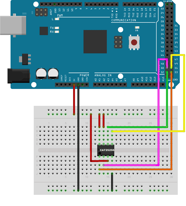
1. Attach the EEPROM to the Arduino board using the following circuit diagram:
   SPI EEPROM pin   | Arduino Mega 2560 pin
 _ _ _ _ _ _ _ _ _ _ _ _ _ _ _ _ _ _ _ _ _ _
      /CS   (pin 1) |  53
      SO    (pin 2) |  50
      /WP   (pin 3) |  5 V
      VSS   (pin 4) |  GND
      SI    (pin 5) |  51
      SCK   (pin 6) |  52
      /HOLD (pin 7) |  5 V
      VCC   (pin 8) |  5 V
 _ _ _ _ _ _ _ _ _ _ _ _ _ _ _ _ _ _ _ _ _ _
Task 2 - Configure Simulink Model for Supported Arduino Hardware
In this task, you will configure the Simulink model for the supported Arduino hardware.
1. Open the arduino_SPI_EEPROM Simulink model.
2. In your Simulink model, click Simulation > Model Configuration Parameters to open Configuration Parameters dialog.
3. Select the Hardware Implementation pane and select your required Arduino hardware from the Hardware board parameter list. Do not change any other settings.
4. Click OK.
Task 3 - Configure SPI Properties of Simulink Model
In this task, you will configure the SPI properties of the model according to the SPI settings supported by the EEPROM.
1. Click Target Hardware Resources > SPI properties.
2. Set the parameters in the SPI properties. As per the CAT25256 datasheet, the EEPROM supports a maximum SPI clock frequency of 20 MHz. The EEPROM latches the input data on the rising edge of the SCK clock and shifts out data on the falling edge of the SCK clock. This behavior corresponds to SPI mode 0 (Clock Polarity 0, Clock Phase 0) and 3 (Clock Polarity 1, Clock Phase 1) on Arduino Mega 2560 as per the Arduino Mega 2560 datasheet. The EEPROM begins to shift the MSB first.
3. Click OK.
Task 4 - Configure Simulink Model to Write and Read Data Using SPI WriteRead Block
In this task, you will configure the model to read data from the EEPROM using the SPI WriteRead block. You will run the model in External mode to view the read data.
1. Open the arduino_SPI_EEPROM Simulink model.
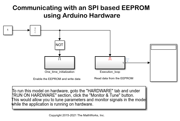
2. Notice the two subsystems in the model:
The One_time_initialization subsystem enables the EEPROM and writes data to it.
The Execution_loop subsystem reads data from the EEPROM.
The One_time_initialization subsystem executes only once at the first step of the execution of the model. For the rest of the execution time the Execution_loop subsystem runs. This selective execution of subsystems is handled using the Unit Delay and the Enabled Subsystem blocks from the Simulink library.
The EEPROM uses the following opcodes for enable, write, and read operations as per the CAT25256 datasheet:
       Command  | Opcode | Operation
    _ _ _ _ _ _ _ _ _ _ _ _ _ _ _ _ _ _ _ _ _ _ _ _
        WREN    | 6      | Enable Write Operations
        WRITE   | 2      | Write Data to Memory
        READ    | 3      | Read Data from Memory
    _ _ _ _ _ _ _ _ _ _ _ _ _ _ _ _ _ _ _ _ _ _ _ _
3. Open the One_time_initialization subsystem and note the following points:
The Chip select (CS) pin parameter of the SPI WriteRead block is set to 53 according to the connection in the circuit diagram.
Before writing to the EEPROM memory, you need to enable the write operations on the device. The Write Enable constant block set to 6 is connected to the SPI WriteRead block. This sends the WREN command to the EEPROM over the SPI bus.
After the WRITE command, send the 16-bit EEPROM memory location that you want to access followed by the data bytes.
The Write constant block with the value of [2 0 10 101:105] sends the WRITE command followed by the 16-bit memory location 10 (0x000A) on the EEPROM. It sends 5 bytes from 101 to 105 to write to the EEPROM.
The delay subsystems provide the delay required for the successful completion of the write operations.
The priority of the delay subsystem (corresponding to the WREN command) is set to 1. The priority of the SPI WriteRead1 block (corresponding to the WRITE command) is set to any value higher than 1. This ensures that the EEPROM is write enabled before sending the data bytes to be written.
To set the Priority of a block, right click on the block > Properties > General > Priority. To know more about block priorities and their impact on block execution order, refer to Specify Block Properties.
4. Open the Execution_loop subsystem and observe the following:
After the READ command, send the 16-bit EEPROM memory location that you want to access. To read n number of stored data, you need to send n number of zeros following the 16-bit EEPROM memory location.
The Read constant block with the value of [3 0 10 zeros(1,5)] sends the READ command followed by the 16-bit memory location 10 on the EEPROM. It sends 5 zeros to read 5 data bytes.
Task 5 - Run Simulink Model in External Mode (Monitor and Tune)
In this task, you will run the model in External mode to monitor the data read from the EEPROM.
1. On the Hardware tab of the Simulink model, in the Mode section, select Run on board and then click Monitor & Tune.
2. In the Execution_loop subsystem, monitor the Display block to observe the data read from the EEPROM.
3. Click the Stop button in the Simulink model to end the External mode execution.
Other Things to Try
Change the SPI mode as per the EEPROM datasheet and your Arduino board. The EEPROM latches the input data on the rising edge of the SCK clock and shifts out data on the falling edge of the SCK clock. This corresponds to SPI mode 0 (Clock Polarity 0, Clock Phase 0) and 3 (Clock Polarity 1, Clock Phase 1) on Arduino Due as per the Arduino Due datasheet.
Change the SPI clock frequency to a different value supported by the EEPROM.
Follow the steps in this example to communicate to other SPI devices.
You can also select a web site from the following list:
Americas
- América Latina (Español)
- Canada (English)
- United States (English)
Europe
- Belgium (English)
- Denmark (English)
- Deutschland (Deutsch)
- España (Español)
- Finland (English)
- France (Français)
- Ireland (English)
- Italia (Italiano)
- Luxembourg (English)
- Netherlands (English)
- Norway (English)
- Österreich (Deutsch)
- Portugal (English)
- Sweden (English)
- Switzerland
- United Kingdom (English)