Event-Based CAN Message Transmission Behavior in Simulink
This example shows how to use event-based CAN message transmission in Simulink® with Vehicle Network Toolbox™. This feature allows for CAN and CAN FD message transmission when a change in data from one time step to the next is detected.
A configuration option available on the CAN and CAN FD Transmit blocks enables transmission on data change. When enabled, messages of particular CAN IDs transmit only when the data changes for that ID. Each message is independently processed in every time step based on its ID. When disabled, block operation and periodic transmit operation function normally. In addition, the event-based transmission can be enabled along with periodic transmission to have both work together simultaneously.
Prepare the Example Model
The included example model contains two CAN Pack blocks configured into a single CAN Transmit block. One message's data is a constant while the other is a counter that changes at every time step.

Open the example model.
open EventTransmitPrepare the CAN Database File Access
You can access the contents of CAN DBC files with the canDatabase function. Through this function, details about network nodes, messages, and signals are available. This DBC file is used in the model and is used to decode information sent from the model.
db = canDatabase("CANBusEvent.dbc")db =
Database with properties:
Name: 'CANBusEvent'
Path: 'C:\Users\jpyle\Documents\MATLAB\ExampleManager\jpyle.21bExampleBlitz\vnt-ex59902587\CANBusEvent.dbc'
Nodes: {'ECU'}
NodeInfo: [1×1 struct]
Messages: {2×1 cell}
MessageInfo: [2×1 struct]
Attributes: {}
AttributeInfo: [0×0 struct]
UserData: []
A test node is defined in the DBC file.
node = nodeInfo(db,"ECU")node = struct with fields:
Name: 'ECU'
Comment: ''
Attributes: {}
AttributeInfo: [0×0 struct]
The node transmits two CAN messages.
messageInfo(db,"Constant_Msg")ans = struct with fields:
Name: 'Constant_Msg'
ProtocolMode: 'CAN'
Comment: ''
ID: 10
Extended: 0
J1939: []
Length: 4
DLC: 4
BRS: 0
Signals: {'Constant'}
SignalInfo: [1×1 struct]
TxNodes: {'ECU'}
Attributes: {}
AttributeInfo: [0×0 struct]
messageInfo(db,"Counter_Msg")ans = struct with fields:
Name: 'Counter_Msg'
ProtocolMode: 'CAN'
Comment: ''
ID: 20
Extended: 0
J1939: []
Length: 4
DLC: 4
BRS: 0
Signals: {'Counter'}
SignalInfo: [1×1 struct]
TxNodes: {'ECU'}
Attributes: {}
AttributeInfo: [0×0 struct]
Execute the Model with Event-Based Transmission
Enable Event-Based Transmission Only
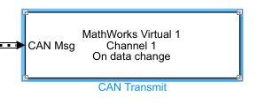
Enable the event-based transmission in the CAN Transmit block programmatically. Also, disable periodic transmission.
db = canDatabase("CANBusEvent.dbc")db =
Database with properties:
Name: 'CANBusEvent'
Path: 'C:\Users\jpyle\Documents\MATLAB\ExampleManager\jpyle.21bExampleBlitz\vnt-ex59902587\CANBusEvent.dbc'
Nodes: {'ECU'}
NodeInfo: [1×1 struct]
Messages: {2×1 cell}
MessageInfo: [2×1 struct]
Attributes: {}
AttributeInfo: [0×0 struct]
UserData: []
set_param('EventTransmit/CAN Transmit', 'EnableEventTransmit', 'on');
set_param('EventTransmit/CAN Transmit', 'EnablePeriodicTransmit', 'off');
Note that the block display changes after applying the settings.
Configure a CAN Channel in MATLAB for Communication with the Model
Create a CAN channel using virtual device communication to interface with the Simulink model. Also, attach the CAN database to it to automatically decode incoming messages.
canCh = canChannel("Mathworks","Virtual 1",2)
canCh =
  Channel with properties:

   Device Information
            DeviceVendor: 'MathWorks'
                  Device: 'Virtual 1'
      DeviceChannelIndex: 2
      DeviceSerialNumber: 0
            ProtocolMode: 'CAN'

   Status Information
                 Running: 0
       MessagesAvailable: 0
        MessagesReceived: 0
     MessagesTransmitted: 0
    InitializationAccess: 1
        InitialTimestamp: [0×0 datetime]
           FilterHistory: 'Standard ID Filter: Allow All | Extended ID Filter: Allow All'

   Channel Information
               BusStatus: 'N/A'
              SilentMode: 0
         TransceiverName: 'N/A'
        TransceiverState: 'N/A'
       ReceiveErrorCount: 0
      TransmitErrorCount: 0
                BusSpeed: 500000
                     SJW: []
                   TSEG1: []
                   TSEG2: []
            NumOfSamples: []

   Other Information
                Database: []
                UserData: []
canCh.Database = db;
Start the CAN channel to go online.
start(canCh);
Run the Model
Assign a simulation run time and start the model.
t = "10";
set_param("EventTransmit","StopTime",t)
set_param("EventTransmit","SimulationCommand","start");
Wait until the simulation starts.
while strcmp(get_param("EventTransmit","SimulationStatus"),"stopped")
end
Wait until the simulation ends.
pause(2)
Receive Messages in MATLAB
Receive all messages from the bus generated by the model.
msg = receive(canCh,inf,"OutputFormat","timetable")
msg=12×8 timetable
    5.204 sec    10    0    'Constant_Msg'    [5,0,0,0]    4    1×1 struct    0    0
    5.204 sec    20    0    'Counter_Msg'    [0,0,0,0]    4    1×1 struct    0    0
    5.206 sec    20    0    'Counter_Msg'    [1,0,0,0]    4    1×1 struct    0    0
    5.206 sec    20    0    'Counter_Msg'    [2,0,0,0]    4    1×1 struct    0    0
    5.206 sec    20    0    'Counter_Msg'    [3,0,0,0]    4    1×1 struct    0    0
    5.206 sec    20    0    'Counter_Msg'    [4,0,0,0]    4    1×1 struct    0    0
    5.206 sec    20    0    'Counter_Msg'    [5,0,0,0]    4    1×1 struct    0    0
    5.206 sec    20    0    'Counter_Msg'    [6,0,0,0]    4    1×1 struct    0    0
    5.206 sec    20    0    'Counter_Msg'    [7,0,0,0]    4    1×1 struct    0    0
    5.206 sec    20    0    'Counter_Msg'    [8,0,0,0]    4    1×1 struct    0    0
    5.206 sec    20    0    'Counter_Msg'    [9,0,0,0]    4    1×1 struct    0    0
    5.2061 sec    20    0    'Counter_Msg'    [10,0,0,0]    4    1×1 struct    0    0
Stop the CAN channel in MATLAB®.
stop(canCh);
Explore the Message and Signal Data Received
The number of times a CAN ID has been received is plotted below. The message "Constant_Msg" (CAN ID 10) is received only once because its data does not change after its initial setting. The message "Counter_Msg" (CAN ID 20) is received from every time step because the data changed continuously in it as the model ran.
% Define X and Y axis.
x = 1:length(msg.ID);
y = msg.ID;

% Plot the graph for both the CAN IDs received.
stem(x,y,'filled')
hold on;
yMax = max(msg.ID)+5;
ylim([0 yMax])

% Label the graph.
xlabel("Number of CAN messages");
ylabel("CAN ID");
legend("CAN ID","Location","northeast");
legend("boxoff");
hold off;
![]()
Next, plot the signals received in each message over the same simulation run.
% Create a structure with signal details.
signalTimeTable = canSignalTimetable(msg);

% Plot the signal values of "Constant_Msg".
x1 = 1:height(signalTimeTable.Constant_Msg);
y1 = signalTimeTable.Constant_Msg.Constant;
plot(x1, y1,"Marker","o");
hold on

% Plot the signal values of "Counter_Msg".
x2 = 1:height(signalTimeTable.Counter_Msg);
y2 = signalTimeTable.Counter_Msg.Counter;
plot(x2, y2,"Marker","o");

% Determine the maximum value for y-axis for scaling of graph.
y1Max = max(signalTimeTable.Constant_Msg.Constant);
y2Max = max(signalTimeTable.Counter_Msg.Counter);
yMax = max(y1Max,y2Max)+5;
ylim([0 yMax]);

% Label the graph.
xlabel("Number of Times Signals Received");
ylabel("CAN Signal Value");
legend("Constant","Counter","Location","northeastoutside");
legend("boxoff");
hold off
![]()
The signal "Constant" (in message "Constant_Msg") is plotted only once, while the signal "Counter" (in message "Counter_Msg") is plotted for every time step. This is due to event-based transmission being enabled in the CAN Transmit block, which transmits a CAN message only if data has changed for that CAN ID compared with the previously received message.
As the signal in message "Counter_Msg" is a counter, which increments by 1 at every time step, a linear curve can be seen for it.
Each data point represents a transmission with event-based transmission enabled, hence signal "Counter" is received at every time step, but signal "Constant" is received only once.
Execute the Model with Event-Based and Periodic Transmission
Enable Both Transmission Modes
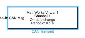
Enable the event transmission in the CAN Transmit block programmatically. Also, enable the periodic transmission and set a message period.
set_param('EventTransmit/CAN Transmit', 'EnableEventTransmit', 'on');
set_param('EventTransmit/CAN Transmit', 'EnablePeriodicTransmit', 'on');
set_param('EventTransmit/CAN Transmit', 'MessagePeriod', '0.1');
Note that the block display changes after applying the settings.
Configure a CAN Channel in MATLAB for Communication with the Model
Create a CAN channel using virtual device communication to interface with the Simulink model. Also, attach the CAN database to it to automatically decode incoming messages.
canCh = canChannel("Mathworks","Virtual 1",2)
canCh =
  Channel with properties:

   Device Information
            DeviceVendor: 'MathWorks'
                  Device: 'Virtual 1'
      DeviceChannelIndex: 2
      DeviceSerialNumber: 0
            ProtocolMode: 'CAN'

   Status Information
                 Running: 0
       MessagesAvailable: 0
        MessagesReceived: 0
     MessagesTransmitted: 0
    InitializationAccess: 1
        InitialTimestamp: [0×0 datetime]
           FilterHistory: 'Standard ID Filter: Allow All | Extended ID Filter: Allow All'

   Channel Information
               BusStatus: 'N/A'
              SilentMode: 0
         TransceiverName: 'N/A'
        TransceiverState: 'N/A'
       ReceiveErrorCount: 0
      TransmitErrorCount: 0
                BusSpeed: 500000
                     SJW: []
                   TSEG1: []
                   TSEG2: []
            NumOfSamples: []

   Other Information
                Database: []
                UserData: []
canCh.Database = db;
Start the CAN channel to go online.
start(canCh);
Run the Model
Assign a simulation run time and start the model.
t = "20";
set_param("EventTransmit","StopTime",t)
set_param("EventTransmit","SimulationCommand","start");
Wait until the simulation starts.
while strcmp(get_param("EventTransmit","SimulationStatus"),"stopped")
end
Wait until the simulation ends.
pause(5);
Receive Messages in MATLAB
Receive all messages from the bus generated by the model.
msg = receive(canCh,Inf,"OutputFormat","timetable")
msg=22×8 timetable
    4.598 sec    10    0    'Constant_Msg'    [5,0,0,0]    4    1×1 struct    0    0
    4.598 sec    20    0    'Counter_Msg'    [0,0,0,0]    4    1×1 struct    0    0
    4.5987 sec    20    0    'Counter_Msg'    [1,0,0,0]    4    1×1 struct    0    0
    4.5987 sec    20    0    'Counter_Msg'    [2,0,0,0]    4    1×1 struct    0    0
    4.5987 sec    20    0    'Counter_Msg'    [3,0,0,0]    4    1×1 struct    0    0
    4.5987 sec    20    0    'Counter_Msg'    [4,0,0,0]    4    1×1 struct    0    0
    4.5987 sec    20    0    'Counter_Msg'    [5,0,0,0]    4    1×1 struct    0    0
    4.5987 sec    20    0    'Counter_Msg'    [6,0,0,0]    4    1×1 struct    0    0
    4.5987 sec    20    0    'Counter_Msg'    [7,0,0,0]    4    1×1 struct    0    0
    4.5987 sec    20    0    'Counter_Msg'    [8,0,0,0]    4    1×1 struct    0    0
    4.5988 sec    20    0    'Counter_Msg'    [9,0,0,0]    4    1×1 struct    0    0
    4.5988 sec    20    0    'Counter_Msg'    [10,0,0,0]    4    1×1 struct    0    0
    4.5988 sec    20    0    'Counter_Msg'    [11,0,0,0]    4    1×1 struct    0    0
    4.5988 sec    20    0    'Counter_Msg'    [12,0,0,0]    4    1×1 struct    0    0
      ⋮
Stop the CAN channel in MATLAB.
stop(canCh);
Explore the Data Received
Plot the data received in each message over the same period.
% Create a structure with signal details.
signalTimeTable = canSignalTimetable(msg);

% Plot the signal values of "Constant_Msg".
x3 = 1:height(signalTimeTable.Constant_Msg);
y3 = signalTimeTable.Constant_Msg.Constant;
plot(x3, y3,"Marker","o");
hold on

% Plot the signal values of "Counter_Msg".
x4 = 1:height(signalTimeTable.Counter_Msg);
y4 = signalTimeTable.Counter_Msg.Counter;
plot(x4, y4,"Marker","o");

% Determine the maximum value for y-axis for scaling of graph.
y3Max = max(signalTimeTable.Constant_Msg.Constant);
y4Max = max(signalTimeTable.Counter_Msg.Counter);
yMax = max(y3Max,y4Max)+5;
ylim([0 yMax]);

% Label the graph.
xlabel("Number of Times Signals Received");
ylabel("CAN Signal Value");
legend("Constant","Counter","Location","northeastoutside");
legend("boxoff");
hold off
![]()
The plot shows that the signal "Constant" in message "Constant_Msg" is received only a few times; once at the start due to the event-based transmission, and later due to the periodic nature of the transmission. This is because the input value to the signal is kept constant.
While the value for signal "Counter" changes at every time step in the message "Counter_Msg", it is received continuously due to the event-based transmission, and later there are a few more transmissions because periodic transmission is enabled.