
Advanced Electrical System Algorithm Development Techniques
Overview
AI Workflow for Battery State Estimation
State of charge (SOC) estimation is among the most important tasks of a battery management system (BMS). SOC estimation is typically performed by current integration or using a Kalman filter. In this session, we will describe an alternative method based on AI. A deep neural network is trained to predict SOC based on voltage, current, and temperature measurements. The resulting network is then implemented in Simulink® and incorporated into a closed-loop BMS model. Finally, C code is automatically generated from the net for hardware implementation on an NXP S32K3 board used in PIL mode.
Deployable Algorithm Development using Model-Based Design
The rapid growth in the complexity of electrical systems is pushing companies to adopt Model-Based Design and operate at higher levels of abstraction. This design approach offers numerous advantages, such as shortening development time through earlier verification and validation, automatic code generation, and abstraction of hardware architecture. Moreover, Model-Based Design also provides hardware deployment solutions for micro-controllers, FPGAs, and SoCs. This talk will explore the capabilities to implement algorithms into various hardware platforms.
Highlights
- Develop AI-based Battery SOC Estimation
- Workflow – From Data Acquisition to Hardware Deployment
- Code generation capabilities for various hardware platforms
About the Presenters
Dr Emmanuel Blanchard is a senior application engineer at MathWorks who first joined the company as a training engineer in 2014. He focuses on data analytics. Prior to joining MathWorks, he was a Lecturer in Mechatronic Engineering at the University of Wollongong. He holds a PhD in Mechanical Engineering from Virginia Tech. He also worked as a Systems / Controls Engineer at Cummins Engine Company and as a research assistant in several research institutions in California and Virginia.
Dr Ying Chen is a Senior Application Engineer in the discipline of radar design, signal processing, and wireless communications. Ying has experience in both academic and industrial research institutions related to satellite communications and radar signal processing. Her research interests include RF front-end distortions, signal processing, and software-defined radio. Besides her research work, Ying has also worked on various industrial prototyping and field-tested projects including satellite communication systems, passive and active radar systems.
Alex Shin holds the position of Principal Application Engineer at MathWorks, where he specialises in providing support to projects in the areas of simulation, verification, and automatic code generation, primarily for commercial projects. He has been actively involved in defining the simulation and code generation process and implementing Model-Based Design tools in large organizations. Mr. Shin holds a Bachelor's degree in Mechatronics Engineering from the University of New South Wales.
Recorded: 16 Mar 2023
I'm an application engineer. I've been at the company for eight years and a half now. And again, my background is in mechatronics. I mention that again, because I think my background reflects the evolution seen in many industries. Many traditional workflows have evolved due to the advances in the field of AI.
So I worked in the automotive industry in the past. And I used common filters for different purposes. And AI was not used very much back then. But things have changed now. And my current job reflects that. AI has become an alternative method for many different tasks. So that includes battery state estimation.
So state of charge estimation, also called SOC is among the most important task of a battery management system. And it's typically performed by current integration or using a Kalman filter. And this presentation will describe an alternative method based on AI. So we're going to have a deep neural network that is trying to predict the state of charge. So it's based on voltage, current, and temperature measurements.
And the resulting network will be implemented in Simulink and incorporate it into a closeup battery management system model. And finally, the C code will be automatically generated from the network for hardware implementation using an NXP board here. So that's using process and a loop.
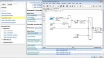
So let's get started. Let's actually start from the end here. So what you see here is a Simulink model. And we're going to deploy a set of charge estimation based on a neural network on a NXP target board. So here you pick the NXP target. You say no.
And the end goal, I mean, it's hardware deployment of a possible alternative to the traditional Kalman filter methods or set of charge estimation in battery. So this entire presentation is going to attempt at describing how to get to this final point.
And so, you see the simulation here. It's running. You see the current and what is temperature. And you see the estimation and the error estimation versus real. And now, after simulation on target, there is a possibility to provide the execution to have an assessment of how well a suitable several AI methods are for the set of charges submission in a diploid state. So you see a report here.
So there are three main things, three main ideas here. And the first one is we know that estimating the state of charge in batteries is very important. And the idea here is to evaluate whether there's room for improvement versus the traditional Coulomb counting and Kalman filter methods that AI methods could bring to the table.
So measurements that are typically available from a battery pack are voltage, current, temperature. And they can be applied to estimate the estimation of the set of charge. So what I'm going to do here is to describe briefly step by step of what it takes to go from data acquisition all the way from a battery measurement, then the selection of AI methods.
So that's parameterization. And then testing. And then, finally, implementation in Simulink, so with the set of blocks that I wanted to talk about. And then, finally, for generation for hardware deployment at the end.
So at the end, we have a brief notion of how to compare different methods in terms of accuracy, deployability, and so on to see what works best. Not very much needed here in terms of an introduction. I just want to say that SOC is not something that we measure directly. We need to measure something else. And using a model of the battery, We can estimate the set of charge.
The problem with this definition, which is the one here on the left, the integral of the current, is that the problem is that we measure current with the sensor error. That's unavoidable. If we don't take care of the resetting, the calculation for the estimation, it's going to drift up over time. And after a while, it's not going to be very useful.
So how do you take care of that? The typical approach to that kind of resetting is a Kalman filter. So Kalman filter is a method by which we combine estimation done by Coulomb counting and measurement done by real voltage measurements in order to do that resetting. And it does that very well, actually, in a recursive method.
So the nice thing about the Kalman filter is that it's been in use for many decades. It's been very well understood. It's very accurate. But it has a limitation. We need to have a very good dynamic model of the system under consideration.
And that is very important. It can be challenging, in some cases, like, for example, at very low temperatures of operation for the batteries. That's one of the things that people are considering as well. Is there room for improvement. And what can AI bring to the table in that case?
So of course, it's a little more computationally intensive than merely integrating the current. So let's keep that in mind.
So how about, instead of relying on a very sophisticated model of the battery that I use instead of the Kalman filter, how about instead taking a more black box approach, AI approach, and trying a statistical method with signals that are available in the battery pack to estimate that state of charge?
So I get a bunch of inputs. You see the three inputs on the left. And my input is the state of charge. And I just did a black box that describes a relationship between inputs and output. And then I test that on all the data sets to see how well that works, compare that to the real answer.
So the potential of that AI method is that we wouldn't need such an accurate battery model. A data, you may know, requires a lot of experimental characterization. And secondly, when the training is done on real data from a real battery, the thing is, we can measure a real battery in the lab and train the neural network with that with data there. So that's an advantage too, if you can do it in a lab.
And supposedly, too, another thing is, in the case of neural networks and other AI techniques, they're capable of capturing any kind of nonlinearities. Many times, very often it's too difficult with a model-- dynamic model.
And the thing is, so it's a black box approach. So one of the drawbacks is interpretability is not necessarily easy if you go to interpret. And some of them may be computationally intensive. That depends on what type of AI models that they need to be. You can try some small ones first. But if they get too big, with respect to the alternative, it might be computationally intensive. So that's something that you need to evaluate as well.
What do we do to create an AI-based associate immersion method? The first thing we need is data. So we need real data from a battery. We acquire the data in a lab. And the second thing we need to do after that is determine what kind of AI method is the most suitable. So it could be a neural network, such LSTM, or feed-forward neural network. It could also be something from classical machine learning methods, like decision tree, SVMs, et cetera. It really depends on the case. So we could try different things and see.
And then, typically, we have our battery management system implemented in Simulink. So if I have a set of charge estimation function trained in MATLAB or somewhere else, the question is, can I bring that into Simulink? And the answer is yes. There is a block that behaves like a neural network. And funnily, the last part here, code generation, so the C code generation for deployment of hardware for processing in the loop and embedded implementation in general as well.
So going back to the problem at hand, let's estimate a state of charges in AI. It all started on this particular project. So it was outside of MathWorks. It was at McMaster University. And they published a paper a couple of years ago, describing a way in which they did this using a feed-forward deep neural network.
So what did they do? Well, they acquired the data from different kinds of batteries. Then they measured current, voltage, and temperature. And they use that to find a fit forward neural networks.
So you see it here. You can do that interactively in MATLAB. We have an app. It's called a Deep Network Designer app. And it can generate MATLAB code. So you can pick a network architecture, and in terms of training options, et cetera, using that app.
And then, still using the same app, you can push train and test. And when you're happy with that, well, you have your neural network trained. And you use that to make future predictions.
So let me talk a little bit about our tools here. Because one thing I would like to mention in this presentation is that AI is a lot easier than you probably think. And that's thanks to our apps, you don't need to be an expert. So the main approach is try to reuse models already exist out there for similar applications. But then retrain them on your own data.
So we have nice tools to do that, to visualize what you will import, and want to reuse. And sometimes you might want to make a few modifications, for instance, the size of the network at the beginning it needs to be at the right number of inputs. You might change your layer at the end, et cetera.
Well, in that case, we have some nice tools here to look at it and detect errors, which is really nice, because if it's only lines of code, and searches don't match, or one layer appear somewhere and shouldn't be in front of another type of layer, it's difficult to debug. But here you just look at it, you get the error messages, and make your modifications.
So I'll show you on another example, which is visual images, because I think it's easier to see that on LSTMs, how you can use these apps. And my message is, don't be scared of AI.
So you open this app and pick something that's nice for your application. In this case, we're going to recognize images, pizzas, hot dogs, et cetera. So SqueezeNet is a good choice. The thing is trained for different type of images, not necessarily pizzas et cetera.
So what's nice is you can visualize the models, see the number of neurons you have, et cetera. If you're an expert, you could also draw something you've said. But usually that's not what you're going to do if you are a beginner in AI. But again, you can make some modifications. So this tool is nice because you can see a few meta-errors.
Then you import your data. So in this case, we have folders with different type of food data. And you can see it here, like French fries, pizza, sushi, et cetera. And finally, here, you pick some options to train your network. So this is a tough part if you don't know deep learning. How do you pick the right initial learning rate? So the things at the top are the most important there.
So you can try different things on train. But if you're not an expert, it will depend on these options at the top. And see here, validation accuracy, 28%, that's not so great at recognizing different type of foods. So well, when you're done, you can generate a code from that and reuse it. But the thing is, it wasn't great. So if you're not an expert, what do you do?
Well, you can actually use a brute force approach. A lot of it really is trial and error. So we have this app, Experiment Manager here, where remember the initial learning rate, we don't really know what to pick if you're not an expert. Well, just use the different values are there and train that in parallel.
And at the end, it's just trial and error. It's an art. It's not a science if you're new to it. And even if you know it really well, I mean, we experiment all the time because every data set is different. So you can create some experiments in a MATLAB code, import that in the app.
And then, let's say I have some parameter sweeps. Let's say I want to try different initial rates. So I run all that in parallel. Keep track of the work, what accuracy I get, how long it took to train the network, et cetera. And here I see 89%.
So look. You don't even know why it works best. But this is what works best. And just reuse that. And then turn that on, you reuse it on future images to make predictions.
So a few practical concerns here. Deep learning can take a very long time. So we have a crowd support and third party integrations. So you can move the training to the appropriate compute platform. It could be a GPU, a public cloud, a private cloud, and so forth.
The point is that a single model in MATLAB can be moved to the appropriate compute platform. That can save you in an enorm of development time-- enormous amount.
Another thing I'd like to mention, we also know that the deep learning community is incredibly active. There are new models coming out all the time. You might want to use a new one out there.
But it might be in another platform, like TensorFlow and PyTorch. We can import models from these platforms, and also other platforms via ONNX, Open Neural Network Exchange. So you have access to these models and can work with them in a MATLAB environment. You could also import them in Simulink.
So if something already exists, and it's not in MATLAB, reuse it, and then use MATLAB for what is good at-- good for, like deployment, augmentation, optimization, our tools, our visual tools, to visualize, debug, et cetera. We make it very easy to code if you don't have your own code.
Summarize the modeling steps, in MATLAB you can have access to all the algorithms and methods used to develop models. Then you work with them at the core level or through an app. I think this is our strength. You import these models but use MATLAB apps to train, or record, et cetera. And you can also accelerate training using different computing platforms. So you can take advantage of what's out there in the community.
Now that I explain how you work on the AI part, let's go back to this specific SOC example. Because McMaster University opted for feed-forward neural network, which is not recursive, but for SOC estimation, we need information about the past.
So what they did is they augmented the input data set by including moving averages of the voltage, current, et cetera. And oh, these two actually only. Sorry. And then they give their feed-forward neural networks the notion of memory doing that. So the state of charge was accurately calculated in the lab because they can measure the current very precisely in there.
But what they got was actually quite impressive. Very impressive results at low temperature, which is nice because that's the weak point in the Kalman filter, that's really where we struggle before. So very good results on that front. So that's the main upside here, of the story here.
But how about the Simulink side? I was telling you before that if you have a BMS system, in Simulink we can select from the Simulink library blocks and have a AI models in there. So we can import neural networks. One has been set up in MATLAB, I mean in Simulink.
The only thing you need to do is to parameterize it with the name of the model you gave it when you trained it. And as long as the input signal to that block has a dimensionality that is compatible with the neural network, what it is expecting, the output is going to give you the state of charge.
So that was a general notion. So here's a Simulink model. So that's open loop here. It's showing you what I just mentioned. And it's also showing you different variants of systems, different type of AI models that you could try at the same time, and also the Kalman filter. So you can test all of them at the same time from the same model by just saying which method you want.
So I want in here to compare the simulation accuracy, and the estimation accuracy, and the efficiency, and so on. And everything can be done from the same Simulink model. So you see here at the top on the right you know how well it's working. You see the true value versus the estimate.
And the last part of the story is, well, how about everything is working nice in MATLAB, and it's working as in Simulink. That's great. But let's say I need to incorporate that to my batter management system model. How do I put in a microcontroller if it's feasible to implement in the field? So I can generate planned library free and standard C code to target a microcontroller.
So this example here, this is what we did with an NXP controller-- the C code generation. And with that, we're back to our original statement. We configure the Simulink model to talk to the right board. Let me play the video here. So you see it here. We're going to Settings. And you're going to pick the right board. That's the IO configuration, NXP.
Then after that, I'm going to go to software in the loop, processor in a loop, so you see it here run SIL and PIL And C code is generated from the blocks that contain the AI model. So that's what you see in the video. It's accelerated a few times here because of time constraints. It actually takes longer. And I can do processor in the loop execution on target.
So you can see that here, closing up the entire workflow. And at the end of the process loop simulation, I can open this report. You can see it very soon. It gives me some ideas of what the performance KPI is of the code was running-- that was running on target. So the execution time and so on, I can look at all that now.
So the quantitative comparison of some of the AI functions that we use, I could be a little bit more quantitative here, but I didn't really have enough information. For example, to parameterize the Kalman filter in such a way that the comparison was actually completely fair. But anyway, this is what we thought we could share here as a means to describe how to compare different methods.
What you see is a feed-forward neural network, so what they use at McMaster University, it seems to strike a good balance between accuracy and execution time. So the LSTM network on the right was very accurate. But it runs significantly slower. It's more complex mathematically.
So yeah. I think the FFN, feed-forward neural network, is a very good compromise. Is better inference speed than EKF, work better as low temperatures, something we mentioned. Of course, it's less interpretable. But it gives you better results.
So with that, I conclude, we presented an AI-based battery state of charge estimation method. We shared the workflow that it takes to develop this AI-based method from data acquisition all the way to code generation and hardware deployment as well. And finally, we compare different methods. So the feed-forward neural networks seem to strike a good balance between accuracy and execution time. So it was well worth the effort.
Thanks very much for attending. And in the next presentation, my colleagues Ying and Alex will focus on the deployment part using model-based design. So they'll be reusing the same battery management system with a controller. This is it.
Thank you very much.
Model-based design reduces development time by providing simulation environment for system design, early detection of errors, and fast implementation of your algorithm running on production devices. In this session, my colleague Ying and I will share how algorithm models could be deployed to various devices during the development lifecycle.
OK, Ying. Let's start with model-based design workflow.
Thanks for the introduction, Alex. Before we start talking about model-based design, you might want to know, well, why do we need to use model-based design? So let's have a look at some of the megatrends that are influencing the direction of system development now.
The first one is electrification. It's often tied to electrical vehicles and green energies. Second one, connectivity. It's not just connecting everyone now, where I actually want to connect to everything electronically as well.
The third one is autonomous systems. Where a lot of attention is on autonomous vehicles, but it also includes the automation of factories, warehouses, and defense systems. And the last one, artificial intelligence. This is the game-changer for many industries in changing what the system can do and offer new capabilities some were not possible before.
No matter what technology you're working on, there is one trend that is universal. And that is to grow your system complexity. Systems are exponentially more complex than they were just a decade ago. Jaguar Land Rover estimated 1 billion lines of code will be needed for the autonomous vehicles, which actually, if you read this article, is about 10,000 times the amount of code used in Apollo 11. And all of that code needs to be tested to ensure that these systems are reliable and safe.
These days, many products are designed by the new model-based design method, such as smartphones, washing machines, cars, and even aircrafts. So what are the differences though? Here is a schematic view of a traditional design workflow. Generally, you will start with a requirement definition, like the behavior of the system, performance targets, or safety limitations.
Then you will start to design your system. Different team will work on different components of the system, such as control, mechanical, and the electrical part. They are possible to use in different tools as well. So on this stage, you can only at best test each of these components separately, but not the whole system.
Then to test your algorithm, you will need first to code manually and then get a prototype of your mechanical and electrical hardware to perform some tests and finally evaluate the overall behavior and the response of your controller.
So this type of process have some strong limitations. First, during this design stage, you cannot perform test of your fully integrated design because models are not executable and the design environment is not assigned for each part. As a result, the interaction between different systems cannot be tested. And this also have a direct impact on the validation. If you are unable to test full system, you cannot validate your design against the requirements.
Another big point in this graph is on the control part. You have to perform manual coding to implement your control algorithms on your target. And this phase is time-consuming and may introduce human errors. And finally, for the hardware part, you will only be able to test and find possible problems when you will get prototypes which are generally expensive, potentially not robust, and usually available quite late in the process.
And just imagine, you might need to do some testing that possibly damages them. Because we can only perform testing of the full system very late in this design workflow, this conventional design process make design iterations a lengthy process, especially for issues across two or more design domains.
With model-based design, the main challenge will occur in the design stage. Indeed, you elaborate a model of your system in a single environment. You can test each component separately but also the fully integrated design. This means that you can perform closed-loop testing of your system early in your design process. And so, you can find errors and optimize your system already in this stage against requirements.
The second idea about the controller part is to reuse the models you developed during the design stage and automatically generate code from it to implement it on your target. For the hardware part, you will also be able to reuse your model in order to perform hardware your loop test before having a prototype of your hardware.
And of course, because you are able to test your design at each stage of your development, you will perform continuous test and verification to validate the design and ensure that your design are not introducing errors.
Here is the example of battery management model in the Simulink environment. Well, you can see that my model is divided into two main components. And I think this is the first big thing. Even if you're not familiar with Simulink, models are easy to read and to understand. It is an efficient way to communicate.
In here, you will find the first part of the model which correspond to the BMS electronic control unit, where you will find all your control algorithms. Well, in this part, you will find the plant, the battery model. In this block there are physical model of the battery and its components in order to simulate its electrical and thermal behavior.
Well, in the controller, you will find functions which calculate current and power limits of the battery, the state machine where we define the operating modes, and also the state of charge estimation and the balancing logic to check cell voltage and enable balancing if needed.
For the hardware or the plant part, you will also find several sub-subsystems. And the first one, of course, is the battery pack, including cells, that are the heart of the battery. But there's also pre-charged circuits as well as charger and load drive. I'm not going to go to detail about these systems. The main purpose we want to build this model is to simulate our system and perform testing and validation.
So let's have a look at the simulation results. Well, we can connect this model to a test harness. Then by sending different BMS state request signal we can simulate the battery behavior at different conditions. Now we can pull out information like cell temperature, cell voltage, balancing states, battery pack current, state of charge estimations, as well as the BMS stats.
Then, after we have these results, we can compare the simulation results with expectations and verify or improve our systems. So by using a simulation demonstrated in the previous example, you can check whether your design fulfilled all the system requirements. You can simulate the whole system together to discover any integration issues early. OK, Alex, how could this model help us in implementation?
Thank you, Ying. Now let's look at how model-based design supports deployment of your algorithms onto different hardware at various stage of your development. Here is an example lifecycle of a deployable algorithm development project.
You'll typically start with an idea which evolved to early prototyping testing. And once the project progresses, you'll have your final product and hardware to test on your hardware. And while you're testing your hardware, you'd like make sure you have automated hardware and software validation environments.
So the hardware used in this lifecycle can be mapped into different use cases. In today's session, we'll use three categories. The first part is rapid control prototyping. The second category is on using production intended hardware. The last part is what's called real-time testing. Now, let's start by looking at rapid controls prototyping.
So here is the workflow for the rapid prototyping. Let's say you have a model with your algorithm as well as your simulation environment. So in the rapid prototyping environment, we assume that you already have real hardware or system that you can actually test.
So what happens here is that you generate code on your algorithm and run on what's called target computer hardware. But these target computer hardware needs to be connected to your system and then test using real wire and signal connections. And you'll have capability to monitor your target computer hardware.
The key advantage of rapid control prototyping is that you can test your control system with actual hardware to test your system. And you don't have to do final embedded controller development or integration with your product and system, and quickly, easily test your algorithms. Not only that, the environment provides capability to monitor all the signals in your algorithm as well as tune the parameters. But that's the real algorithm development early in the development stage.
Now, let's quickly look at an example hardware setup. So you have your host computer with MATLAB and Simulink running. And once your hardware to be deployed is complete, you press deploy button, and the model will be running on a real-time target computer.
So usually, the connection between the host computer and the real-time target computer is done by the ethernet cable. And depending on your physical system that you're testing, you may need to use various different connections based on your test requirements.
So from this example model, when we press Run on Target button, our code generation tools will automatically generate code, compile, and download to our real-time hardware environment. And after doing that, Simulink will establish connection between the actual hardware and the model. As you can see, you can control the actual hardware from the Simulink interface as well. And we also provide other ways to control the real-time hardware.
So these blocks represent inputs coming from the hardware. So by using one of signal monitoring tool, data inspector, you can actually see data being streamed back to Simulink in real time. If we actually change some value, you can see that it's actually being applied to controller.
So that was a quick overview on rapid control prototyping using Speedgoat as an example. The key advantage here is really to test your algorithm with the hardware without requiring the final embedded controller or the final production controller that you intend to use for your final system. It allows you to quickly focus on your algorithm development while the hardware is being prepared.
Now, the second category of hardware deployment support is use of evaluation board based on production intent hardware. Model-based design supports automatic code generation. We support C, C++ code generation, GPU generation, PLC, as well as FPGA. So all these providers will often have what's called evaluation board using the same microprocessors, FPGAs, so that you can quickly test their product.
And Simulink provides support on deploying algorithms on many of these evaluation tools. Just like rapid prototyping helps you to focus on your algorithm development without worrying too much about actual basic software or the platform software development, at the same time, given that you're using same microprocessors or the final chip that will be used for your production, actually testing your algorithm on the chip that will be used for your final device.
Here is an example model configured to generate code for an evaluation board. So at the top, you see blocks that will help you configure different settings for your devices. And the green part represents input and output of your evaluation board. And the blue part represents the application algorithm that you are developing.
Here is an example model that we'll be using to target an evaluation board. So in this particular example, we are using an evaluation board from NXP. As you can see, we have blocks help us configure different options on an NXPs microcontroller. We have peripheral configuration as well as MCU peripheral controls. In this particular example, we ADC and CAN communication configured to run on the evaluation board.
So in this function called triggered subsystem, triggered by ADC, contains our actual algorithm that we are testing on the evaluation board. As you can see, based on certain conditions, we are writing to digital output as well as writing data up to CAN messages.
Once the model is ready, now we can automatically generate code and deploy on the evaluation board. Once the code generation is complete, you'll see code generation report on the side. And you can trace from the generated code to the original model. It's bidirectional traceability from the code and from the model.
This workflow also allows you to download the compiled code into the evaluation mode. Once your executable is downloaded into microcontroller, you can actually see the hardware running. And you can use either Simulink to monitor the execution of the algorithm, or use NXP's interface to monitor signals in the algorithm. As you can see from this example, we are actually changing the value using a nob on the evaluation board.
So that was an example on running the algorithm models on an evaluation board. It's typically based on production intent hardware. So the key advantage here is to focus on the actual key algorithm design and also shorten the iteration based on use of automated code generation. And given that you are actually testing on the production intent hardware, the behaviors that you see over here is expected to carry over to your final hardware.
Now let's move to the last category, which is real-time testing. So we often use what's called hardware-in-the-loop testing for the real-time testing of your production intent hardware. Now, this is the workflow for hardware-in-the-loop testing. So here is an example. It has an algorithm controller as well as the simulation environment, including plant, test input, as well as verification criteria.
Now, from this model, expecting that actual algorithms now generated and deployed to your production intent hardware. Now, for the rest of the model-- this could include plan, test environment, as well as the verification criteria, is now deployed into target computer hardware.
And this target computer hardware is connected to your production intent hardware. Given that it's a fully controlled environment, you can automate multiple test cases as well as introduce conditions that are difficult to produce on real system testing.
Here is an example setup of the hardware-in-the-loop testing. Again, we have host computer which runs MATLAB and Simulink connected to a Speedgoat machine, in this case, by ethernet. And the Speedgoat machine is now connected to your final production hardware.
Just like the previous environments, given that this setup is also connected to a host computer which runs MATLAB and Simulink, you can automatically run all your requirements-based tests and understand whether your final deployment will pass this requirements.
There are a number of different options when it comes to Speedgoat real-time hardware configuration. Depending on your requirements of performance and interfaces, you can choose the right one for you. And if you need to have a setup representing your entire vehicle, you can combine these together to form a rack, they will effectively simulate your entire vehicle.
Now our Speedgoat machines do have powerful GPUs. But if you need to run algorithms in high frequency, we also provide workflow to deploy your algorithm or test cases into FPGA. Given that the setup is being used by many different industries, we do support common protocols used by different industries such as automotive and aerospace. And it comes with different options that you can easily connect to different actuators and sensors and power equipment that you use.
So that was a quick overview on real-time testing based on hardware-in-the-loop testing. But the key advantage here is that you can validate your embedded controller without requiring the real system and the test. You can also run automated test and closed-loop environment and inject faults that are very difficult to produce in real system under test.
Now, there are a number of ways to start using hardware support that you saw today. First method is to visit our web page that you see on the screen and look for the hardware that you're interested to use. If you already have MATLAB license, there is an add-on menu that will help you to easily navigate through different hardware options available.
Model-based design enables fast implementation of system design and also provides capabilities to detect errors early in the development cycle. During the simulation, you can achieve hardware-independent development of your algorithm. But as your project progresses, you can also have hardware-aware development environment.
To learn more, we provide interactive tutorials and training courses relevant to today's contents. Thank you very much for your attention.
Featured Product
Embedded Coder
Up Next:


Related Videos:


Select a Web Site
Choose a web site to get translated content where available and see local events and offers. Based on your location, we recommend that you select: United States.
You can also select a web site from the following list
Americas
- América Latina (Español)
- Canada (English)
- United States (English)
Europe
- Belgium (English)
- Denmark (English)
- Deutschland (Deutsch)
- España (Español)
- Finland (English)
- France (Français)
- Ireland (English)
- Italia (Italiano)
- Luxembourg (English)
- Netherlands (English)
- Norway (English)
- Österreich (Deutsch)
- Portugal (English)
- Sweden (English)
- Switzerland
- United Kingdom (English)