Design of Autonomous and Unmanned Aerial Systems | Next Generation Aerospace Series
From the series: Next Generation Aerospace Series
Overview
The application of Unmanned Aerial Systems (UAS) with different levels of autonomy is widening in sectors like agriculture, construction or defence. The development of autonomous UAS requires the collaboration of several technology domains, connecting system engineers and algorithm designers with multi-disciplinary skillsets (including communications, controls, perception or motion planning, among others) in the same working environment. New programs where collaboration is the key can benefit from early proof-of-concept simulations to reduce risk, cost, and rework before flight testing.
Highlights
In this one-hour session, learn how you can use MATLAB® and Simulink® in integrated development workflows for autonomous UAS applications that span from early system design and simulation to deployment and test, including:
- Developing system level and design level models in a common working environment
- Proofing concepts early with simulation and rapid prototyping
- Evaluating autonomous algorithms for self-awareness and situational awareness with simulations
About the Presenters
Christian Merkl is an application engineer at MathWorks in Munich. His background is in aerospace engineering with more than ten years of professional experience in industry and research. At MathWorks he focuses on Model-Based Design and workflows for safety critical applications.
He started his carrier in industry, working on flight mechanics studies and the development of an electrical UAV. Parallel he was a researcher at Technische University Munich and specialized on system identification algorithms for flight control design. Christian received his PhD in aeronautical engineering from the TU Munich in 2019.
Juan Valverde is the Aerospace and Defence Industry Manager for the EMEA region at MathWorks. His technical background is on the design of dependable embedded computing solutions for aerospace.
Prior to MathWorks, Juan was a Principal Investigator for Embedded Computing at the Advanced Technology Centre for Collins Aerospace - Raytheon Technologies in Ireland. Juan has a PhD in Microelectronics and Computing Architectures by the Technical University of Madrid (Spain).
Recorded: 10 Feb 2022
Hello, everyone. Today my colleague Christian Merkl and I will be talking about some important trends in next generation aerospace programs and how they are impacting the design of autonomous and unmanned aerial systems. But first, let me introduce myself and let my colleague Christian do the same.
My name is Juan Valverde. I'm the Aerospace and Defense Industry Manager for EMEA MathWorks. I'm located in Germany, in Munich and I have been working for MathWorks for almost two years now. Before coming to my MathWorks, I worked at the Research Center for Collins Aerospace in Ireland focused on dependable embedded computing solutions. Hello Christian.
Hello Juan and hello to the audience. My name is Christian Merkl. I'm an Application Engineer at MathWorks and I work with aerospace customers on autonomous systems. Before joining MathWorks three years ago, I worked in industry and did a PhD in Aircraft System Identification. Today I will present more details on what it takes to develop next generation autonomous and unmanned aerial systems.
Great, so let's begin. So before we enter into the different design stages for UAS, I'd like to provide some context about what we see currently happening in some of the next generation AR space programs. We are seeing how more and more these programs go beyond individual system design to cover really complex system of systems. Therefore, for these programs to be useful and successful, it is necessary to enable proper ways of collaboration among the different entities.
Having common working environments will enable collaboration and artifact exchange at the different abstract levels and within the different stages in the development lifecycle. This is covering from mission to component design. In such complex systems, it is not possible to leave integration tasks for later stages. So different proof of concept will be very valuable when integration can be shown using different fidelity levels. In these new programs where the focus is system of systems, data plays a critical role. Having the right data at the right time in the right asset and how this data is consumed by the pilots to enable efficient man machine teaming is very, very important.
Of course, having the right data in an ultra connected environment will impose many challenges for security. Overall system complexity and collaboration make it crucial to have a digital continuity. For that, model based design techniques are very beneficial as we will see. Traditionally, the different systems design stages have been highly disconnected. This starting from having requirements and specs on documents that are difficult to share, difficult to analyze and difficult to obtain or how bridging system designs and implementations where each iteration is time consuming and prone to errors, it is difficult to calculate completeness and consistency to requirements et cetera.
Or even the use of manual code that is very often difficult to re-use. It is again time consuming and the lack of common languages between domain experts and software or hardware engineers is always posing a problem. Of course, the fact of leaving most of the testing to later stages in the design cycle also challenges traceability, while some design errors are found too late and are very expensive to be fixed. All this discussion makes the relationship between customer and supplier not efficient at all and it is the source of many misunderstandings and contractual conflicts.
The idea of model based design then will be to connect all these different stages and to offer a digital continuity in such a way that all different stages are connected from requirements to implementation. This full connection will allow faster iterations, enable full traceability of your designs and it will allow bring in verification activities a lot earlier into the picture. The use of models with different levels of fidelity will improve collaboration among teams throughout the different project phases.
The need of having well-connected and traceable workflows is even more important when talking about safety critical systems. And this is even more important when these critical systems will work autonomously. Of course, not all unmanned systems will be fully autonomous but a certain degree of autonomy will be expected in most of them. In this slide, we can see an example of the well known OODA loop. The OODA loop is a good representation of the steps to follow to take effective decisions not necessarily done only by autonomous systems, also by pilots.
The OODA loop involves collecting relevant information, recognizing potential biases, deciding and analyzing possible actions and acting and then repeating all the process and correct it. In the presentation today, we will see most of these parts. How observation and situational awareness will be critical for the design of aerial systems to build an accurate picture of the situation. For that this will involve the use of many sensors, sensor fusion and data coming from different assets, through for example communications.
Then in the Orient phase, we will understand what barriers might become an impediment to continue with the rest of the loop. This is connecting and seeing the world as it really is. This will involve aspects like object detection, tracking algorithms and so on that we will see today. Then once you have the data to see where you are and how you are, you should be ready to make an informed decision whether this is taken by the pilot or by the system itself.
It is the process of selecting the next actions to be taken what is in this step. This will involve planning activities of course. Now, there is of course a difference between deciding and acting. The last part of the loop will put into practice the previous stages and correct them through more iterations of the loop. Of course, a good system is a system where iterations of the OODA loop can be done fast. Therefore, connectivity and efficient implementations will be crucial as we will see.
Now that we have introduced a bit what is happening in the next generation aerospace systems and we have seen some general challenges and requirements for our design workflows, let's see what trends we are observing with regards to UAS usage. We are seeing how the use of UAVs for mapping and surveillance activities is growing. This can go from border surveillance to the rain mapping for agriculture for example.
We're also seeing how these systems are used to monitor critical infrastructure, how they are used for delivery or even how they're used for critical rescue missions together with helicopters. And of course, the role they are playing as the remote carriers in the future combat air system. Now as we all know, their design is not an easy task. So we will need to deal with complex algorithms to cover different parts of this OODA loop that we explained. From sensor fusion to object tracking to control loss. But it will not be only the algorithms, but how to integrate everything so that it makes sense for the mission. What is a real problem.
And always ensuring quality of course and having in mind most applications will be safety critical.
In the next part of the session, we will see tools and methods to ease the design of unmanned material systems. We will see how these methods are integrated and covered from concept to implementation. And we will see different comprehensive ways for validation and verification. For that, my colleague Christian will guide you through the different steps. Thank you Christian.
This session will step through an overall integrated workflow enabled by MATLAB and Simulink to design, simulate, test and deploy your UAV application. We'll introduce tools to help you in designing UAV systems and autonomous applications while discussing appropriate methodologies based on your UAV development tasks and needs.
Evaluating UAV systems in the virtual environment is a key aspect of reduced rework and costs of target tests. And we will show how closed loop simulations within the models can enable you to ensure your system quality on your desktop computer. We'll cover these solutions through explaining an integrated workflow for developing UAV applications with MATLAB and Simulink. And this workflow will span from defining your system architecture, modeling a UAV platform, whether it's a new platform or you're modeling an existing UAV.
Design the algorithms to make your system autonomous. Than verification and validation of your UAV systems and algorithms design to assess your design early. Integrated simulations of sensor models will then allow you to virtually test your UAV application in a closed loop simulation. After determining that the system performs as expected in integrated simulations, you will go from virtual to real world and automatically generate code for hardware implementation. In this time, you'll be able to perform hardware flight tests by connecting to the UAV hardware to monitor the system mid-flight.
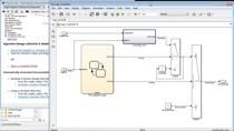
Lastly, of course, there is a need for flight data analysis so that you can evaluate the system and make iterations as necessary. We'll begin with a brief overview to system architecture. Now, in the beginning of the workflow, the system architecture will be designed based on the requirements definitions. System Composer is a recent tool that provides capabilities to design and analyze system and software architecture in the MATLAB and Simulink ecosystem.
With this, you can system architecture, allocate requirements to architecture model components for traceability and investigate your design. A typical challenge is that there's often a need to put the architecture design between different tool environments. With a System Composer you can integrate the model based systems engineering and software architecture modeling within the Simulink workflow for model based design, allowing for streamlined processes which maintains traceability.
With System Composer you can run trade studies to compare different system variants based on power budgets of similar size and weight or power analysis. Additionally, it gives you the flexibility to eventually connect dynamic simulation models in the same environment and utilize them for your system analysis.
These models can include, for example, models of the system dynamics of a UAV. So for the modeling of the UAV, the recommendation is to select the appropriate model fidelity level based on your specific task involved with your UAV project. If you're building a new UAV platforms, you may have need to provide more detailed modeling of your UAV. In other words, a high fidelity model of a UAV platform design. If you're focused on developing autonomous applications for UAV, it may be sufficient to start off an approximate model of the UAV.
Now, there's a trade off here as a more detailed model is the more processing which can take more resources in terms of simulation time. Whereas an approximate model will be able to execute quickly but will not include all the detailed UAV components. So if you're building your UAV platforms or systems and will be creating high fidelity models, physical modeling as a method supports to build your UAV models by using and connecting physical components rather than equations.
Through the add on Simscape products, you can build models of these components such as bodies, joints, motors and other various physical components and also have the ability to import UAV models to provide a quick baseline to start your physical modeling activity.
Airspace blocks that provides a riot methods to monitor UAV vehicle dynamics and you can put high fidelity models for Stokes equation of motion models to determine how you reposition velocity attitude and other related values.
Additionally, a slightly approximated modality method is also provided with body equations of motion blocks. And you can even include environmental effects to your model such as wind and atmospheric effects.
And on the more approximate side for modeling UAVs, UAV Toolbox provides the guidance model, blocks for simulating the approximated autopilot controller, as well as the vehicle dynamics for fixed wing or UAV.
So you can set up parameters for the UAV. You will be using and get started right away for simulating the UV to focus on designing the autonomous algorithms.
Again, the recommendation is that depending on whether you're building a new UAV system or more focused on developing the autonomy of UAVs, MATLAB and Simulink provides efficient methods for creating your UAV model at the appropriate fidelity level for your specific task.
So whatever these models looks like for your application, it's a foundation for the development of the autonomous algorithms that guide your system through its environment.
Autonomy for UAVs involves the technology components perception, planning and decision and controls. So how does this look like? Imagine you have a UAV at a given starting location. It needs to navigate through the surrounding environment to get to a target endpoint. So the UAV will need to perceive and understand its own location as well as what's around the UAV itself.
The UAV will then plan an optimized path through the surrounding obstacles and it will receive control commands for the UAV to fly and follow the planned path. Let's break this down to autonomous technology components. First for perception. This really involves self awareness and situational awareness. For self awareness, the UAV needs to understand where it is during its flight. In other words, localization.
Sensor Fusion and Tracking Toolbox is an add on product that provides sensor models such as IMU and GPS. But it can be used to design localization algorithms that fuse data from multiple sensor sources. You can also simulate and generate synthetic data from the virtual sensors to test your algorithms in various scenarios, even including what if cases such as events where sensors fail during the flight.
Simultaneous localization and mapping or SLAM algorithms are often used to build maps and localize the UAV at the same time. Navigation Toolbox provides capabilities to implement multi-sensor SLAM algorithms with interactive tools to design, modify and analyze your SLAM solutions. There is also an interactive SLAM map builder app to help you step through the process in applying SLAM solutions.
On the other slide are situational awareness. This is necessary for the UAV to recognize and understand its environment in which it's flying. This involves processing image data from camera sensors as well as point cloud data from LIDARs, and typically also includes using deep learning techniques to recognize and identify objects and/or terrain elements.
Finally, sensor calibration is a typical challenge when using LIDAR and camera outputs together to accurately interpret objects in a scene. LIDAR Toolbox provide capabilities and interactive apps to estimate transformations between LIDAR sensor and camera. The interactive apps are very helpful to execute these tasks in a hands on manner, and you can even export and share the sequences of steps performed within the app.
Moving on to planning and decision. This encompasses the motion planning for the UAV. Now on the simple side, UAV Toolbox provides methods to define UAV missions through waypoint following, orbit following and customizable path planning algorithms. This is helpful when there is a predefined path with the UAV we will fly so that you can quickly define this path with waypoints and simulate the mission.
For more advanced UAV motion planning, you can use path planning algorithms provided in Navigation Toolbox such as RRT or RRT star so that you can define the start and goal states for the UAV and use the algorithms to calculate the path through a given environment. There are also metric tools to evaluate whether the path is valid and has proper obstacle clearance or smoothness. So you can design these planning and decision algorithms within the MATLAB and Simulink ecosystem depending on what type of motion is needed.
Now I'll step into controls. Of course, model based design is very strong in developing control systems. Recently there's an increase in research and application of advanced controls such as model predictive controls and reinforcement learning for UAV trajectory planning and tracking. These advanced control algorithms benefit from the model based design process by being able to incorporate the UAV model into simulations. These advanced controls are applied for optimization, for generating shortest path or safe condition free trajectories, minimizing energy consumption and other aspects.
And products such as model predictive control toolbox and reinforcement learning toolbox helps you to develop these advanced control algorithms and includes examples such as a autonomous UAV using non-linear model predictive controls for trajectory tracking and also training a controller using reinforcement learning with a Simulink planned model as a remote training environment.
After building the UAV model and designing autonomous algorithms, verification and validation is the next critical step to evaluate whether you have designed correctly according to requirements and to test the design to check that there are no errors. After you have created the UAV model and autonomous algorithms, MathWorks offers various capabilities to evaluate your system. These include requirements traceability that allow you to link specific requirements to components of the model as well as test cases to ensure that the model is associated to requirements and that the requirements are implemented in the model.
Test management and automation of test execution can be done with Simulink Test or you can define your test cases and design test scenarios through interactive tools, automate execution of the many test cases required and automatically evaluate their results based on defined pass/fail criteria. Evaluating the completeness of your test is also important and you can calculate metrics such as model coverage so you can check that you're exercising all portions of your model with the test cases as well as the capability to check that the model complies to specific rules.
Of course, you can automatically generate reports as necessary. These verification and validation tests are especially important for certification workflows such as that for T0179C and applicable qualifiable tools can streamline those certification efforts. An example is provided to step through verification and validation activities with a UAV package delivery example. With this example, you can examine how requirements are linked to modeling components and test cases using Simulink requirements and view the metrics for allocating requirements to ensure the modeling is complete.
Then the Test Manager tool from Simulink Test is used to configure the automated testing and evaluating of results. The interface shows the overview of requirement allocation along with the test results, which includes verification status in which green and red bars indicate passing or failing. This is a great example that you can utilize to get started with implementing verification and validation workflows in the context of UAV application development.
Here's another example from a customer who has applied this workflow to develop a UAV system. In the example, the customer could reduce the development effort and could find 95% of the software bugs before the first flight. This helped the customer to increase the model fidelity and isolate remaining bugs with high precision. The result was a safer, more reliable and higher quality product.
When you talk about situational awareness before, we saw that the UAV needs to have an understanding of its surroundings. To acquire that, usually sensors like RADAR, LIDAR or cameras are used. To include these sensors in closed loop simulations and test autonomous algorithms, we need a virtual environment to simulate with the sensor models. There are various methods to perform such integrated simulations. The range from the Cuboid simulation environment introduced with the UAV Toolbox through co-simulation simulation with the Unreal Engine simulator.
Again, it's important to select the appropriate method depending on your task or stage in your development process. The Cuboid simulations are beneficial in early stages to quickly define scenarios and perform investigations for autonomous algorithms. Also, Cuboid simulations are a powerful tool for developing localization, path planning or obstacle avoidance algorithms allowing you to perform closed loop simulation using sensor models for INS, GPS and LIDAR.
Starting with R2021A release, you can also import custom terrain data to build realistic Cuboid scenarios which include terrain elevation data. The Unreal Engine co-simulation capabilities allows for closed loop simulations in a photorealistic 3D environment. In the Unreal Engine co-simulation UAV simulation with sensor models can be performed to provide synthetic sensor data for LIDAR and camera sensors as well. These high fidelity simulations can be used for more detailed testing of autonomous applications, especially with included perception.
The R2021A release brings the capability to add weather effects off the user photorealistic 3D simulations with Unreal Engine. You can add effects such as rain or adjust the position of the sun which affect the camera sensors data so we can perform virtual testing of the perception algorithms in a variety of weather scenarios.
The integrated closed loop simulations with sensor models opens up opportunities to investigate and develop autonomous applications without real world data by allowing the use of synthetic sensor data from simulations. One use case is for building a 3D map using simulated LIDAR point cloud data. By executing the photorealistic 3D simulation, we can obtain a synthetic point cloud data from the LIDAR model. The synthetic data can be processed including extracting and matching features to registering and aligning point clouds.
Real world challenges such as drift which affect localization can be investigated and you can see how the initially created map may be skewed due to the drift. Then you can apply solutions for detecting loop closure in the flown path, create post graphs and optimize process to check whether you're mapping algorithm is working correctly. This helps to investigate, evaluate and tune your algorithms prior to automatically generating code for the applications and proceeding to hardware.
For the 3D photorealistic simulations with Unreal Engine, we ship predefined scenes. Customizing scenes is possible, adding your own terrain data and ground objects as needed to simulate your individual mission. Of course, when flying it 30,000 or 40,000 feet you probably will not need detailed models of buildings or urban canyons. For other missions, you can use and customize these scenes. RoadRunner is an interactive tool that provides capabilities to design 3D scenes which can be used for the Unreal Engine simulation and also for a variety of other simulators or gaming engines such as Unity.
The RoadRunner offers a library of readily available 3D models and can be applied to your scenes.
That was an introduction to integrated simulations with sensor models in a virtual 3D environment. We will now go through the remaining workflow components and Juan will continue with this next step, which is the deployment to hardware.
Thanks a lot Christian. In the previous sections, we have seen how the architecture of the system can be defined and analyzed. We have seen how to model and work with different fidelity levels. We have seen the importance of the different steps in the OODA loop in terms of perception, planning, decision making controls et cetera. We have seen how to integrate all the methods and how all the different sensors and scenarios.
Now a very important part is how this becomes a reality. Using coders, it will be possible to automatically deploy algorithms into target devices, including different types of processors and commercial autopilot hardware. This way, it will be possible to connect implementations and models and see how all work together and validate behavior. Code can be generated of course for CPUs, FPGAs and GPUs.
A frequent question when modeling these kind of systems is how similar my model is to my final implementation. Knowing that in my final implementation I might be using some complex SOC devices to take care of all perception and control algorithms altogether.
In Simulink, it is possible now to simulate your algorithms and bring important features from your hardware and software architectures. This is say communication channels, memories, scheduling sets, et cetera, to make simulations much closer to the final implementation.
Then for several supported targets, it will be possible to fully generate and push the code to the devices and then later monitor and profile what is happening to improve possible iteration.
So finish with this block, I would like to mention a couple of use cases from our users that might be of interest. First, we can see how Korean Air used model based design to design and simulate their flight control and operational logic algorithms. How they used our tools to verify models and generate production code. And how they used our hardware in the loop capabilities to test their implementations.
Some remarkable results you can see ion the image are how they drastically eliminated some errors and how development time was cut more than half. Another very interesting example to highlight is how BAE systems used our tools to enable teams working in different locations to successfully design a UAV autopilot system. They used the tools to modify existing software, generating automatically new code and reducing tasks time significantly. This was used for the Eagle 150 platform.
Thank you Juan for this overview of the different options to deploy your algorithm to hardware.
With the algorithms running on your UAV hardware, it is now time for flight testing. For that, you can connect Simulink to your UAV hardware to send and receive data. For example, to monitor your system during flight tests. You can connect to your UAV and ground control stations such as ground control through the MathLink communication protocol to send and receive MathLink messages during the flight. You can read ROS messages using ROS toolbox or receive data from other data links.
After testing, lastly it is time for data analysis. Post flight data analysis as a necessary and critical activity which includes a couple of aspects. The first is flight log analysis to ensure that your UAV was operating correctly and that it was flying on the correct paths. It's a core element for any flight test campaign and you can use the interactive flight log analyzer app from UAV Toolbox to import, visualize and analyze flight log data.
As an example, you can easily focus on a specific section of your flight to investigate responses and determine whether algorithm updates are necessary. Also, payload data analysis may be relevant if your system has onboard sensors like RADAR or LIDAR that gather data during your flight.
You can apply image processing and computer vision techniques based on deep learning onto the payload data for semantic segmentation mapping or multispectral image analysis.
At that, we have seen the entire workflow for developing UAV applications with MATLAB and Simulink. Starting with architecture design Composer, and model based design to the deployment to hardware and flight testing.
I now invite you all to try out yourself how you can make your system autonomous with MATLAB and Simulink.
Thanks Christian and thanks everyone, for your time today. This was the last part of our presentation, but I have to say that this is only the first episode of a series of seminars that we are preparing. The seminars will be about next generation aerospace. We will be seeing different challenges and different hot topics on the topic.
In the next episode, we will have an interesting discussion about new challenges in human machine collaboration and you can find the link to the registration page in this presentation. Related to today's presentation, you will find a list of resources about UAS and I hope you find them interesting. And please, do not hesitate to contact us for more information. Thank you everyone and enjoy your day.


Select a Web Site
Choose a web site to get translated content where available and see local events and offers. Based on your location, we recommend that you select: United States.
You can also select a web site from the following list
Americas
- América Latina (Español)
- Canada (English)
- United States (English)
Europe
- Belgium (English)
- Denmark (English)
- Deutschland (Deutsch)
- España (Español)
- Finland (English)
- France (Français)
- Ireland (English)
- Italia (Italiano)
- Luxembourg (English)
- Netherlands (English)
- Norway (English)
- Österreich (Deutsch)
- Portugal (English)
- Sweden (English)
- Switzerland
- United Kingdom (English)