Hardware Deployment and Real-Time Wireless Prototyping | Developing Next-Generation Wireless Communications for Aerospace and Defense
From the series: Developing Next-Generation Wireless Communications for Aerospace and Defense
Learn about features in MATLAB® and Simulink® for deploying, prototyping, and testing wireless communications systems.
Discover how development teams can directly connect their commercial, off-the-shelf (COTS) SDR hardware to MATLAB to test algorithms against real-world signals; and how teams can use Simulink to implement these algorithms on FPGA hardware for real-time prototyping.
Published: 19 Jul 2021
Hello, and welcome to this webinar, Hardware Deployment in Real-Time Wireless Prototyping for Aerospace and Defense. My name is Rob Gressly, and I'm an application engineer at MathWorks on our Aerospace and Defense Team. I'm bored with MathWorks now for about 10 years, and my background is in wireless communications and software-defined radio.
Today's presentation fits in with the larger ecosystem of MathWorks' support for developing wireless systems. In other presentations you might hear about our standards-based toolbox for 5G, LTE, or wireless LAN, tools for modeling the RF frontend, antennas, or phased arrays. Today's presentation is going to be focused on the instrument control toolbox for interacting with RF test hardware, as well as the software-defined radio support packages that allow you to connect to different SDR devices. We'll also touch a little bit on the algorithms that are available to you in the wireless HDL toolbox.
So for today's agenda, we'll cover some introductory material, talk about some of the challenges that go into wireless system development and prototyping, and then we'll cover three main use cases-- over-the-air testing, algorithm validation, and code generation and targeting. Finally we'll provide a summary and some resources for you to get started.
So what's the goal for wireless design in aerospace and defense? The goal is to transition your technology from ideas and algorithms to a working hardware prototype, and then eventually, hopefully, to a program of record. As you go along the way, there are a number of challenges, and some of these are really specific to the aerospace and defense industry. Especially in aerospace and defense, you might typically have relatively small teams that have to span multiple domains in order to successfully implement a wireless design. These domains could include RF, analog-mixed signal, firmware or algorithms to run FPGAs, or embedded software such as SoCs or embedded processors.
Evolving requirements are leading to the need for shortened design cycles. More and more, there has been an increased interest in adapting commercial standards such as 5G or LTE for defense-related purposes. These commercial standards are very challenging, and in many cases, aerospace and defense organizations don't have the background knowledge or are starting to acquire that knowledge to implement some of those commercial standards.
We hear a lot of desire for the ability to reuse algorithms or IP across multiple programs within aerospace and defense, or across multiple hardware platforms. This becomes really, really important when you are transitioning from initial prototypes into a program of record, because in order to produce a functional radio to go out into the field, you might need to transition algorithms to a different hardware platform that's more rugged or has better swap, for instance. So the ability to reuse those algorithms more quickly across hardware platforms is very important.
In today's presentation, we're going to see how doing wireless system development and prototyping within the MathWorks toolchain will enable you to address many of these challenges, making it easier for you to accomplish your design across multiple domains, and especially to reuse algorithms as you move step by step along the development cycle.
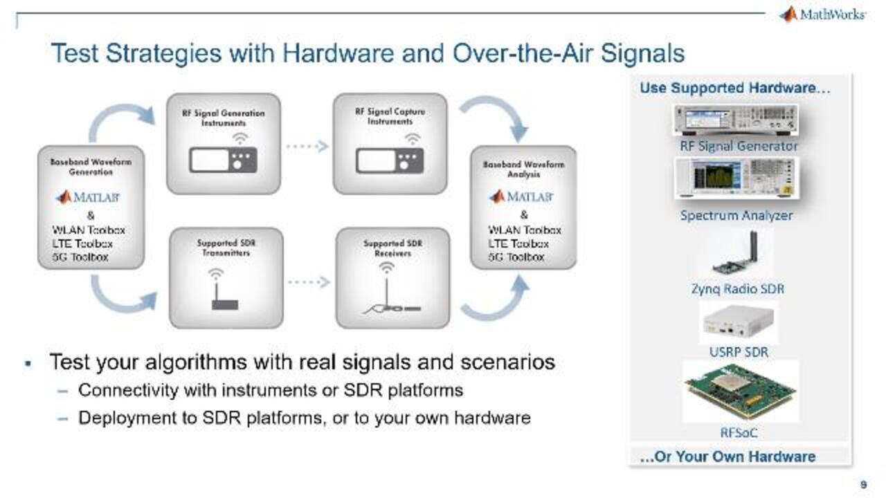
All right. So let's take a look at our first use case, which is over-the-air testing. And what we mean by this is testing your algorithms or your hardware components by actually transmitting or receiving signals over the air. So with MATLAB and Simulink, you can perform over-the-air testing using either RF instruments or software-defined radio hardware. You can transmit, receive, or both.
In the transmit case, MATLAB and the wireless toolboxes are used to generate baseband waveforms. In the receive case, they're used to analyze the captured baseband waveforms. First, let's take a look at the software-defined radio hardware that we support. Through support packages that are provided with the communications system toolbox, you can connect MATLAB and Simulink to Xilinx Zynq-based radios, such as the ADI RF SOM or the Xilinx RF SoC.
You can connect to a number of USRP radios, including the E310, B200, X300, N200, and N300 series radios, as well as two low-cost radio options, including the ADALM Pluto radio, which offers both transmit and receive, and the ultra-low-cost RTL-SDR, which is a receive-only software-defined radio.
In addition to software-defined radio hardware, you could also use the Instrument Control Toolbox to connect to tabletop RF test equipment, such as signal analyzers or signal generators; or other instruments, such as oscilloscopes, network analyzers, or virtually any piece of test equipment that can be controlled using a GPIB or an ethernet interface. This includes instruments from vendors such as Keysight, Rohde & Schwartz, National Instruments, Tektronix, or others.
The Instrument Control Toolbox can be used to, m example, send IQ data using a signal generator and then collect that same IQ data using the signal analyzer. This is a very common workflow for tests and over-the-air validation of wireless signals. In summary, with the Instrument Control Toolbox, you can build test applications to validate your designs.
One very valuable capability or use case for using MATLAB with RF test equipment is the ability to quickly generate a variety of waveforms and push them out over the air. So the wireless waveform generator app, which we provide, allows you to generate a variety of waveforms, including standard-based waveforms, and send them to the signal generator directly from within the app. The app allows you to automatically discover available instruments, transmit or stop infinitely-looped waveforms, and also configure the basic properties of the transmission, including your frequency, output power, and interpolation factor.
Here's a quick demonstration of the wireless waveform generator app in action. So here, we are generating a test model waveform for the 5G new radio standard. So the app allows us to visualize the spectrum, the time domain waveform, as well as the resource grid of our 5G waveform. And then we'll shift over to the Transmitter tab where after the instrument has been searched for, it will identify instruments that are connected to your network by the IP address or the DHCP address. It will allow you to select a driver to communicate with the instrument. The Instrument Control Toolbox has drivers from a number of different instrument vendors.
And then we'll go ahead and set our basic parameters, the center frequency and the output power. Note that our baseband sample rate is listed here. And shifting over to a camera view, looking at the signal analyzer there on the bottom, which is receiving signals transmitted by the MXG or the signal generator up on the top of the screen.
So now when we select Transmit, we are now able to visualize the waveform as it's been transmitted. We also saw the center frequency and the output power change on the top. So we're using the Wireless Waveform Generator app, connect it from MATLAB to these instruments over ethernet, and using that to push out, in our case, a 5G waveform. The Wireless Waveform Generator app will allow you to output LTE, wireless LAN, Bluetooth, as well as a simpler waveform such as OFDM QPSK from directly within that app.
In addition to over-the-air testing, MATLAB and Simulink can also be used in conjunction with software-defined radio hardware for live algorithm validation. So what this means is that MATLAB and Simulink are used to execute the baseband processing as well as the test bench aspects of your design, including signal generation or results verification, while a RF frontend, a piece of software-defined radio hardware is used as a transmitter and/or a receiver. So you are simulating your algorithms using streaming RF data.
One important thing to note is that real-time streaming into MATLAB or Simulink may be possible, but the sample rates will be limited primarily by the transport rate. Typically ethernet between the software-defined radio and the host PC. As well as the host performance of the PC itself, whether it's able to keep up with the data that streaming into the host. The complexity of the host receiver algorithms can also make a big difference here.
Note that in order to work with high-sample rate signals without dropping data, we do allow you to capture contiguous bursts of samples that are then transferred to the host PC and processed in bulk. So there would be some latency there to your design, but that would allow you to work with a higher sample rate signals and perform algorithm validation.
Ultimately our goal with this workflow is to create a simple experience, abstracting a lot of the hardware layer away, and allowing you to quickly configure tunable radio parameters, such as center frequency, sample rate, automatic gain control, and things like that which are dependent on the software-defined radio platform that you're working with. Again, that could include the USRPs or the Zynq-based radios or some of the other hardware that we spoke about earlier.
More and more commonly, it's become necessary either in multi-antenna or MIMO operations to operate multiple software-defined radio hardware devices in order to accommodate multiple channels. So in this case, the Communication System Toolbox support packages allow you to synchronize those radios using a common external clock. And we have several examples of how to do this in the documentation, but if you have a clock signal generator or a PPS signal generator, those can be used to, for example, synchronize multiple USRP X300 radios and allow you to run multi-antenna or MIMO operations from within MATLAB and Simulink.
To demonstrate this algorithm validation workflow, I have an example that uses ADS-B signals to perform airplane tracking. ADS-B stands for Automatic Dependent Surveillance-Broadcast, and it's a standard that is now required on all aircraft operating in the United States airspace as of about a year ago.
ADS-B acts to supplement the traditional radar with additional information and functionality. So traditional radar is denoted by these red lines where we send out a radar waveform, it reflects off of aircraft, and the reflected waveform tells the radar what the aircraft's position is. ADS-B is more of and-- more of an active location technology.
So transmitters on board aircraft will generate packets of bits that contain information about the aircraft's position, its callsign, altitude, et cetera, and the ADS-B transmitters will send those packets to any ADS-B receiver in vicinity. So it could be on other aircraft or it could also be used by air traffic control to augment the traditional radar display.
So in this example, we will use a low-cost software-defined radio hardware, the ADALM Pluto, to receive these ADS-B signals and decode them in Simulink. One nice thing about this ADS-B signals is that they're ubiquitous. Pretty much anywhere in the world, as long as there's airplane traffic, you can connect up a receiver and start receiving these SoC signals on 1090 megahertz. So that's what we're going to do here.
All right. So I've had my ADS-B receiver running here for a little while. That's in this Simulink model here on the left. Where I have a block from the Analog Devices LM Pluto receiver support package that's sending the received signal through a simple implementation of the baseband PHY layer of ADS-B.
And you can see that the bulk of this is made up of MATLAB function blocks for performing a packet search. So ADS-B packets use a preamble to indicate the beginning. So we can search through our received waveform for that preamble, and then we can perform packet synchronization and parsing out of the bits.
Up here on the upper right, we can see a running display of aircraft that we are currently tracking based on their ADS-B position-- or ADS-B message information. Each aircraft has its own ID, which is kind of like its serial number. And then the ADS-B messages in some cases can contain the flight ID or the callsign, which you can see listed here. Additional ADS-B information could include position, altitude, speed, heading, or vertical rate.
You can see here, the total number of packets that we've detected and successfully decoded. Depending on the hardware that you're using, you might get a relatively high or relatively low packet error rate. And then finally down here on the lower right, making use of the MATLAB toolbox to plot and update the position of the aircraft in real-time. So I'm located near Dayton, Ohio, so we can see some of the aircraft that are being tracked. And I can select them here to get additional information about what they're doing.
So let's go ahead and stop this model, and I'll draw your attention to the relevant software-defined radio piece here. First of all, I mentioned how I was using a support package for the Analog Devices Pluto radio to connect to that particular device. If I open up my Simulink library browser, you can see that I have a few of the support package libraries installed, including the ADALM Pluto radio and blocks here for performing both transmit and receive.
Now if you have the Communications Toolbox, in order to get access to these support packages for the first time, you'll need to install them. So in order to do that, I can go back to my MATLAB home screen, go to the Add-Ons menu, and then select Get Hardware Support Packages. And then from there, I can search for the software-defined radio hardware that I would like to use or I can also narrow it down here by selecting Wireless Communications.
And you can see a variety of different SDR support packages that are available. Once you find the one for your radio, you can select it, and then go ahead and install it directly from this add-on explorer. The nice thing about this is, it will take care of downloading all of the required drivers, make sure that they're correctly installed, and that they're the correct version. So it's a really nice way to get started very quickly using the software-defined radio hardware.
So going back to my Simulink model, looking at the Pluto radio receiver block, you can see how when I open up, it allows me to specify the radio ID. USB 0 is simply the default. And then configure the center frequency. So ADS-B messages are transmitted at 1090 megahertz. So I specify that here. I can specify the source of gain for these Analog Devices radios. They have a AD9361 RF transceiver on them that has different automatic gain control nodes, or you can specify your own gain.
Most other software-defined radio hardware devices just allow you to specify the gain here. I can select which channels I'd like to use, and then also the baseband sample rate, and the numbers of samples per frame that I'd like to transfer back into Simulink at once. I mentioned earlier how we have this option called burst mode.
If you're working with signals that have a very high sample rate, you can use this burst mode, select the number of frames that are in each burst, and transfer that amount of data of contiguous real-time captured samples back into Simulink for analysis. Additional parameters to select here are dependent on the hardware that you're using, but this particular radio has options for correcting various impairments in the RF signal, and these are selected by default.
So this is how we can start streaming data into Simulink. The hardware support packages also have this capability available from within Matlab. So if I look into the MATLAB documentation here, I'll select my Analog Devices ADALM Pluto radio, and you'll note that in the documentation page, there are options for both Simulink blocks as well as MATLAB functions that allow me to bring the data into my algorithms that are implemented in MATLAB.
Also, all of the software-defined radio support packages provide examples. And I really recommend taking a look at these examples as a way to quickly get started. So you'll see very simple examples here, but also some fairly detailed application-specific examples, such as the airplane tracking one that we just saw, as well as an FM broadcast receiver, wireless LAN transmission and reception, for example. So I definitely encourage you to check out all of the examples for the hardware support packages that you're interested in.
The next workflow step we'll talk about is code generation and targeting. What this means is performing deployment to hardware with real-time data logging and parameter tuning. Previously we saw our algorithms being validated using over-the-air signals, but the algorithms were running within the MATLAB or Simulink environment. In this part of our workflow, we will generate HDL and/or C code for our algorithms and deploy them to an SoC. We'll also have a connection back to MATLAB and Simulink in order to perform test and verification of our design as it's running on the hardware.
There's is a big challenge between developing algorithms at the system level or algorithms running on the host PC and developing algorithms to run on hardware. We might start out with a wireless reference algorithm that makes use of MATLAB as well as various toolboxes for communications or standard-based signals. Because we're in MATLAB, we can make use of floating-point arithmetic, use arrays and use vectors. Typically at this point, we're really focused on refining our algorithms and our signal processing from that perspective. And we're really trying to just verify that our system functionally behaves as expected.
On the other hand, when we go to hardware, you're dealing with another set of design tools. Embedded software languages or for FPGAs, HDL stimulators, synthesis, static timing, place and route, et cetera. Typically on FPGAs, you're working with fixed-point signals, and instead of working with arrays or vectors at a time, you're working with bits that are streaming through the system one at a time.
Entirely different domain knowledge is required compared to developing communication systems. You need to be knowledgeable of digital hardware design and physical implementation. And the architecture is really at a micro level, focused on the design as it's being implemented on the hardware.
So between these two workflows or these levels of fidelity is this wall of abstraction. So we can stay within the MATLAB and Simulink toolchain in order to go through this collaboration process, but it will be a process, so let's talk a little bit about what that process entails. So starting off with a wireless reference algorithm, the first step to take that algorithm down into hardware is going to be starting to add the basic elements of hardware architecture.
For example, if you plan to have part of your design run on the FPGA component of the SoC or the ARM component of the SoC, you would want to have those components implemented as distinct MATLAB functions or Simulink blocks. But you as you go through this architecture collaboration process, you can continue to reuse the same test bench that you have before.
So for example, we can use some MATLAB code to generate a test waveform, as well as using some MATLAB code to verify our results. So as you refine your algorithm and start to introduce that hardware architecture, always continue to rerun those test benches to make sure that you still get equivalent results.
Another very important step is to convert from the vector or frame-based processing of MATLAB primarily to sample-based processing and timing, which can be done in MATLAB, but it also can be done in Simulink. Typically when we see customers go through this workflow, this is the time at which they switch into Simulink, because Simulink, as a time domain system simulator, is a little bit better suited to modeling the timing of different signals.
So for example, adapting algorithms to work on a sample-by-sample basis instead of on a vector of data all at once or starting to include control signals which will determine when frames are valid or when different parts of your design should start to kick off their processing. These will be critical parts of the hardware, so you want to be sure that you model them in software, and again, always be sure to rerun your test bench to make sure that functionally you're still getting the equivalent result.
Next step will be, for the FPGA part of the design in particular, performing fixed-point quantization. So this is going to require figuring out the number of bits and fractional bits that are necessary to have a complete enough precision for the different signals in your design. With MATLAB and Simulink, we have a tool called Fixed-Point Tool that will help you through this process by logging the dynamic ranges of all of your signals and then recommending an appropriate word length or a fractional length for you for those signals if you'd like to use it.
But here, you can see one example after going through that process where we have a digital filter that increases the number of bits in our output. And then we reduce the word size of that before we go into the next step of our design, which is a multiplier. And also, we can see how we influence the DSP mapping by setting the number of bits appropriately, and then reducing the output or size before the next stage.
So these are all important components of hardware that you can model in Simulink and then reuse your test bench to make sure that you're still getting the same results, except now you're going to have a higher noise floor due to that fixed-point quantization. But you still want to make sure that your results are acceptable.
So to help out with the hardware implementation of one of many of these algorithms, we provide the Wireless HDL Toolbox, which has reference applications as well as IP blocks for 5G, LTE, or wireless LAN signals. So these are key building blocks of the different wireless standards that are provided across a variety of devices. So you don't have to reinvent these yourself. You can make use of the Wireless HDL Toolbox and drop these algorithms into your Simulink model and then deploy them on the hardware to run in real-time.
At a high level, here is what the workflow looks like for deploying to SoCs in particular. Here, we've partitioned a very simple Simulink model into two algorithmic components, 1 and 2. Now using our products HDL Coder and Embedded Coder, we will generate HDL code for one of those algorithms, and then C and C++ code for the other algorithm.
Now the generated code isn't the only thing that comes out of this process. What happens is the generated code goes into an existing reference design for whichever hardware platform you are trying to target. So we'll talk a little bit later about the different hardware platforms that have reference designs available. You can also create your own reference design if you have your own piece of hardware that you like to connect to.
But note that this reference design includes access to memory, interconnects with different interfaces, GPIO, analog-to-digital, et cetera. And the code for your algorithms just plugs into the holes in this reference design, but then the connections there are available to you to access the different interfaces in the memory on the board, as well as allowing these algorithms to communicate with one another.
When the algorithms are actually running on the hardware, there are a lot of timing considerations that need to be taken into account. So what's the latency on memory if you need to do a memory access? Or the latency on the AXI registers as you're transferring data from the processor to the FPGA or vice versa?
So for these complicated SoC architectures, we have a tool called the SoC Block Set that allows you to simulate the particular hardware architecture you're targeting, along with the algorithms which you've implemented in Simulink, deploy those designs to Xilinx and Intel devices, and then while the designs are running on hardware, you can do profiling. So determine the performance of software, things like latency, or the hardware utilization of your designs as they're actually running on hardware. So this is another elaboration step that can be used with SoC workflows.
So as an example, we'll take a look at a reference application for a 5G new radio cell search. So the cell search is this orange square here that's being implemented on hardware-- so the FPGA. And some controls are being implemented via software. The input to our reference application is going to be a 5G new radio waveform such as that which can be generated by this line of code from the 5G toolbox. And the output of our reference application is going to be a list of primary synchronization signals, as well as some diagnostic information.
So in Search mode, the reference application will select the strongest synchronization signal block, correct the frequency offset, and then determine the cell ID. Once it's identified the cell ID, it will shift into a de-modulation mode. So it will take the information from the Search mode, including the frequency offset, the subcarrier spacing, and the primary synchronization signal info, and perform off OFDM de-modulation on the receiver waveform and return the results, including the received resource grid and the correlation peaks, as well as diagnostic information in a structure, such as the subcarrier spacing, correlation values, et cetera.
So how that's architected is through this Simulink model. You can see that this model is simply taking in inputs from the MATLAB workspace and sending outputs to the MATLAB workspace. So to execute this model, you can automate it using MATLAB. And in Search mode, we can take a hypothetical 5G waveform here, denoted based on subcarrier and OFDM symbol, and the output of this reference application in Search mode, as I mentioned, is going to be a collection of diagnostic information about the synchronization signals that have been received. And we can also generate plots that show the actual correlation values for each one of the PSS.
So here's a quick little video tour of this model. And then we're going to run it in simulation. So diving into the FPGA portion of this design, on the transmit side, we're just simply generating a hypothetical waveform from memory and then transmit it. On the receive side we have a vector decimator block upfront, which then goes into our cell search algorithm, which has been implemented in Simulink.
Shifting over to the SoC part or the processor part, we can see a task manager as well as an implementation of the receive part of the processor. So now as we're running this model in simulation, we can open up this Simulink Data Inspector and look at all of the signals that are running in our hardware design.
In particular, the state, which is the green line there in the center that's been highlighted, we can see how the state of the reference application changes when we found the PSS signal, when we performed PSS de-modulation, and then finally, the de-modulation of the secondary synchronization signal.
So really, we're performing simulation, but we're performing simulation at a very low level. We're simulating the individual signals running in hardware, the signals have been converted into fixed point, and we have the architecture of the hardware well-defined. To actually perform implementation on the hardware, we're going to make use of the Xilinx support package for the SoC block set, as well as the Communication Toolbox Support package for the Xilinx Zynq-based radio.
Now after performing implementation, code generation, and generating that whole reference design to run on the hardware, we can perform what's called monitoring and tuning. So if you'll see up here on the upper left, we've selected our hardware board as a Zynq ultrascale RFSoC ZCU111. We would use this Configure, Build, and Deploy option to generate code and send the embedded executable and the bitstream to run on the hardware. And now we can use this monitor in Tune mode to connect to the design as it's running on hardware and do diagnostics.
So now as this model is running, we can open up the Data Inspector again and look at those same signals that we saw before. But instead of looking at those signals in simulation, we're looking at those signals as they're actually running on the design itself. We can also extract additional debug information like what we see here, such as the SNR and the decoded cell ID. Again, this is from the design as it's running on the hardware.
So the next step after this would be to disconnect the MATLAB and Simulink diagnostic step once we verify that things are running correctly, and then we'll have a standalone design featuring our algorithms that are running on hardware. So the software-defined radio platforms that are supported for this targeting workflow include the ADI RF SOM, a variety of Zynq-based boards working with the FMCOMMS 2, 3, or 4 data cards from Analog Devices, the USRP Embedded E310, as well as the RFSoC including the ZCU111 Evaluation Kit.
A variety of reference applications are included to help you get started. I'll also say that for this workflow, if you're interested in adopting it, please let us know, because we're happy to provide guided evaluation support for you to help you implement these workflows in these applications for the first time.
All right. Let's wrap up and provide you with some additional resources to get started. To recap, we talked about MATLAB and Simulink as a unified platform for wireless design, including prototyping, through code generation, as well as implementation. You can make use of hardware of different types from different vendors, RF tester instruments using the Instrument Control Toolbox, software-defined radio support packages for algorithm validation or over-the-air testing from the Communications Toolbox, or you can do a full hardware prototyping workflow using our embedded tools such as HDL Coder, SoC Block Set, et cetera.
To get additional information, you can refer to the model-based design for software-defined radio page on the MathWorks' website. So this will provide you white papers, videos, examples, as well as links to all of the hardware support packages that I've talked about today. In particular for the Xilinx RFSoC devices, please make use of the SoC Block Set support package for Xilinx devices page, as well as two simple examples involving transmitting and receiving a tone. Part 1 is system design, and then part 2 talks about deployment. And these are both available on the MathWorks website.
We also offer a variety of training courses in these areas, which you can see listed here. These training courses are available in a number of different formats, including online, self-paced, and instructor-led. They're available in, or if you have a group setting, we're happy to offer customized training courses to meet your needs.
So that concludes today's presentation. I appreciate your attendance and your attention. If you're interested in any of the topics that we discussed today, if you're interested in going into greater detail, please let us know. Thank you.
Featured Product
MATLAB


Select a Web Site
Choose a web site to get translated content where available and see local events and offers. Based on your location, we recommend that you select: United States.
You can also select a web site from the following list
Americas
- América Latina (Español)
- Canada (English)
- United States (English)
Europe
- Belgium (English)
- Denmark (English)
- Deutschland (Deutsch)
- España (Español)
- Finland (English)
- France (Français)
- Ireland (English)
- Italia (Italiano)
- Luxembourg (English)
- Netherlands (English)
- Norway (English)
- Österreich (Deutsch)
- Portugal (English)
- Sweden (English)
- Switzerland
- United Kingdom (English)