Adding a Controller and Plant to the Simulink Model | Getting Started with Simulink, Part 2
From the series: Getting Started with Simulink
Explore how to create a plant control model using Simulink®. The example walks you through how to create both open- and closed-loop systems. You’ll learn how to work with transfer functions, step blocks, and sum blocks.
Published: 23 Oct 2017
This is a very simple model, but at this stage, you're already all set to create your own models. But let's see how to create a somewhat complex model.
Yeah. So what are you thinking, like a plant control model?
A very simple plant control model that using some of the inbuilt blocks instead of building anything from scratch. So let's see how that can be done.
Sounds good. Yeah, it's a pretty common application for Simulink.
Yes. So I'll just shift-drag this block, shift-drag meaning holding Shift and the keyboard but keyboard, and then dragging it with my mouse so that I can add other blocks. Now, if I don't want this block in my simulation, I can simply delete it. But if I am not sure, I can also comment it out, so that I can bring it into my simulation later, if I need it.
So it's like commenting out lines of code in MATLAB. And you can actually see, it's a similar indicator there, the percentage sign. So it's as if it's deleted from your model.
Exactly. So when I'm running my simulations or generating code later on, this block will be ignored by Simulink altogether.
Right.
But it's just there for my convenience. If I just want to turn it on, it's just a single click. I can uncomment it from right here.
Yeah. It's just the nature of building up models. Everything's not going to be perfect. You're going to want to try new things.
Right.
So you know, oh, let me try something else, but I might want to go back to this. So let me drag this off to the side, comment it out, and maybe I'll refer back to it later.
Yeah.
Yeah.
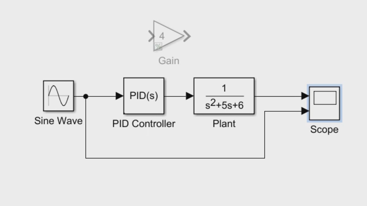
So let me bring in some additional blocks here. I can bring in a plant model, which is essentially a transfer function. As I search for it, I find it in the continuous library. I click it, and it brings up a very basic transfer function for me. So first order, transfer function with the denominator, coefficients just 1 and 1. Just to make it slightly interesting, let me change it to something like 1, 5, 6.
Sounds good.
And that makes this a second order transfer function. Slightly interesting. I can simply bring it and join it to the skull block, if I'm still interested to monitor this signal, which I am. And change this to plant. And you see this line is intersecting with the plant I just created, so I can simply click that signal and auto-route it. So that will take care of not intersecting with the blocks.
OK.
OK. So now, for the plant model, let's bring a PID controller. And search for it. It's available with the continuous library. Spring it in and plug it in between the source and the plant. You can see how the signal connections are pretty straightforward. Simulink is smart enough to-- I understand that if it is aligned with the right boat, you might want a connection, and it would just create a connection for you.
Now, one thing I would do with that signal that goes from the sine waves to the scope, I would actually drag it below, right? This looks a little bit cleaner.
Yeah. Yeah, you are free to move the signals around, but you can also let Simulink auto-route it according to the algorithm for best optimization.
Yeah, so you could adjust it however you want.
Exactly. So once we are done with that, this is still an open loop control. You can run the simulation at this point and just see how it looks like. And also, the other thing is we are using sine wave, and that's probably not the right one.
Oh, yeah. Yeah, sine wave's not a very good impulse, because it's tough to really track what's going on.
Yeah, you can save whether you've achieved steady state.
Yeah, is that a good controller? I don't know.
Right.
So probably a step input is better.
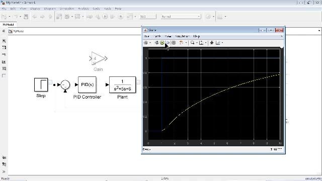
Yeah, so let me delete the sine wave and bring in a step block from sources library. The default value is 1, so I'll leave the step time as 1 and just join it back to my model. And let's run the simulation now. It's still open loop control, but--
Yeah, so not very good, because the blue is the reference. And then, yeah, that's not the best response.
Yeah.
So OK. So we want to have a closed loop system instead, I would imagine.
Yeah, so I bring a sum block. Oh, sorry, I bring a sum block here. And--
With the intention of you're going to take the error. You're going to do a difference here, so--
Yeah, I just look at the difference between the input and the output. And so that the control signal is appropriately sent from the controller to the plan.
OK.
So once I hit that, it changed the sign to minus.
Yeah.
I would like to just drag it here, but since there are multiple ports, it would just not join it, because it doesn't know which port to join it to.
So in this case, you actually have to sever the connection there. But--
But it's not that difficult. Just add it, move the blocks out a little bit if you would like. And then take the signal back and connect it to the plant.
OK.
And bring that signal down here as well. Now, this looks pretty neat.
Yeah, now it's closed loop.
Yeah, and see how the controller behaves now.
Well, it's better.
Yeah.
I still wouldn't say that that's perfect or ideal or--
Right.
You know, could do better than that, I think.
Yes. Yes, for sure.


Select a Web Site
Choose a web site to get translated content where available and see local events and offers. Based on your location, we recommend that you select: United States.
You can also select a web site from the following list
Americas
- América Latina (Español)
- Canada (English)
- United States (English)
Europe
- Belgium (English)
- Denmark (English)
- Deutschland (Deutsch)
- España (Español)
- Finland (English)
- France (Français)
- Ireland (English)
- Italia (Italiano)
- Luxembourg (English)
- Netherlands (English)
- Norway (English)
- Österreich (Deutsch)
- Portugal (English)
- Sweden (English)
- Switzerland
- United Kingdom (English)