Adding Components to Your Simulink Model | Getting Started with Simulink, Part 7
From the series: Getting Started with Simulink
Create subsystems and components in your Simulink® model. Create model references so you or your team can work on components independently from the top-level model.
Published: 23 Oct 2017
So we talked about how right now, this is just one model file. And you can imagine that there's lots of model files. So if you go back to the model itself, I would imagine that one thing we would do is this controller and this plant, they would probably be worked on independently of one another. Maybe one team is building up the model of the controller, another other team is building up a model of the plant. And this top-level model would just reference those things.
So how would we do that? I think it's with model blocks and subsystems.
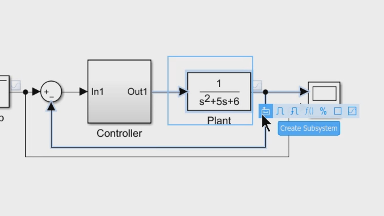
Yeah, subsystems and model blocks are the way to go about doing that. So right now, we have just one block within the PID controller. But imagine there are several blocks. And you can select all those blocks that correspond to that specific function, like controller, in this case. And you can create subsystem using one of these action items that show up, upon selection.
You have a bunch of items here. But I'll create a subsystem using the first action here.
Sounds good.
And that would create a subsystem for me. And if you look inside, it's just the same blocks. In this case, we have only one block. And then it creates input and output ports. And you can name the subsystem.
As controller.
Yeah. And then you can do something very similar to Plant, create a subsystem, just as I did for the controller. And then when I--
Call it Plant.
--double click, it's the same thing. I can call it Plant. And now, we can go one step more from here and create a model reference out of this subsystem.
OK. So, yeah, important point here is that when you're creating these subsystems right here, this is purely a graphical convenience. It's a way to encapsulate lots of blocks. You only did one block here. But you can put any number of blocks inside of these subsystems. And it just makes for a cleaner looking diagram.
What you're going to do now is actually create it so that this is a separate model that can be worked on independently from this top-level model.
Yeah. So I'm converting this subsystem to a model, another Simulink model, essentially. And while doing that, Simulink brings up this Conversion Advisor, which has a few checks that will check for the subsystem properties and then convert that subsystem into another Simulink model. So that becomes a separate component on it's own.
And sometimes, if it finds issues, like this one, like Michael just mentioned, these are just visual convenience. The subsystems are just a visual convenience. It doesn't get treated as a single unit.
Yeah. You actually have to specify that a subsystem is, what we call, an atomic subsystem--
Exactly.
--in order for Simulink to treat it as a unit, let's say.
A separate component on its own.
--yeah, separate component. Otherwise, Simulink doesn't look at it like that. So that's all this Conversion Advisor is saying is, OK, this really needs to be an atomic subsystem before we do the conversion.
Yeah. It says it's a virtual subsystem. And it gives some instructions to make it an atomic subsystem. And I can follow those instructions and do it on my own, or use--
Yeah, the right click, go to Block Parameters. But it's much easier to just click--
The Fix button.
--that.
And the Fix button just does exactly the same thing. It changes the parameter. And then I can hit Continue to continue the conversion process. So once the conversion is done, the block gets updated to another. Similarly model.
Yep. So now it's a model block.
Yeah, if I double click it, it's a completely different, separate model. And it's called plant. And if we go back to our projects, we can actually go to All Files view. And you will notice there are all these other files that get created, in addition to the Plant model, that is not in your project at the moment.
Yeah. So we need to add this back in.
Yeah. But is it just the Plant model? Are there any other files that we are missing? We don't know, right? We know that Plant model is the only one. So we can use dependency analysis for finding all those files. So if I click Analyze, first of all, it tells me that my model is not saved. So I'll go back to my-- sorry, model and just hit Save, and then go back to the project and analyze this again.
And that, then, recognizes that there is another file called Plant that's missing.
It just said it's not in the project
It's not In the project.
So you just add it to the project.
Yeah. Simply right click, add it to the project. And that's all set.
Yeah. So this is a good point because you're not going to be the only one working on this project, at some point. And if others are making changes and you need to know if they've added additional, files or references, or links to the project itself, this is a very handy tool to do that. You see all the dependencies. You've got libraries. You might have scripts. All these other types of things would be shown within the Dependency Analysis view.
Yeah. The nice thing is it also shows generated files. Like if someone generated code, those files also appear here. So even though they are generated, it shows up under Dependency Analysis. So that makes it much more useful.
And we and we see here that before, it only contained three files. Now it does show Plants.
Yep. And it also shows the statuses in project.
Excellent.
And you can then share this project. We have several options. You can zip it and send it to all your colleagues. It happens, a lot of times, you would send a model. You forget the data file. Now you can send the entire project to your team. And you can also send it via GitHub. That's another option if you are using Git as your source control tool. And lastly, what I wanted to show is, basically, we can add additional labels if you want here for that to show up here in your Simulink project too.


Select a Web Site
Choose a web site to get translated content where available and see local events and offers. Based on your location, we recommend that you select: United States.
You can also select a web site from the following list
Americas
- América Latina (Español)
- Canada (English)
- United States (English)
Europe
- Belgium (English)
- Denmark (English)
- Deutschland (Deutsch)
- España (Español)
- Finland (English)
- France (Français)
- Ireland (English)
- Italia (Italiano)
- Luxembourg (English)
- Netherlands (English)
- Norway (English)
- Österreich (Deutsch)
- Portugal (English)
- Sweden (English)
- Switzerland
- United Kingdom (English)