Market Trends and Benefits | How to Use Rapid Control Prototyping to Validate Electric Motors and Power Converters, Part 1
From the series: How to Use Rapid Control Prototyping to Validate Electric Motors and Power Converters
Dr. Carlos Villegas, Speedgoat
Diego Kuratli, MathWorks
Trends for power electronics control design include higher switching frequency requirements for the next generation of semiconductors and increased complexity of control algorithms. Using rapid control prototyping (RCP), you can:
- Validate and adapt requirements before designing the embedded hardware
- Integrate new components easily
- Avoid hardware and firmware revisions
- Employ advanced data logging and parameter tuning
Published: 10 Nov 2021
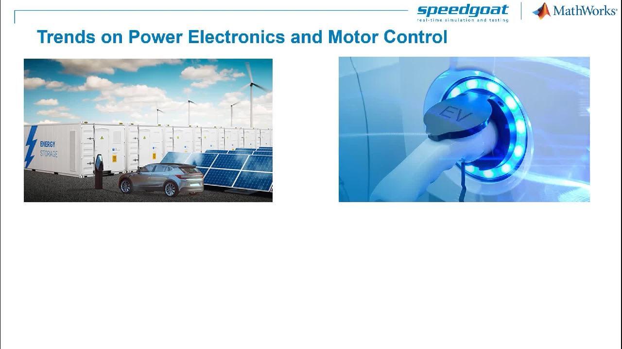
Our electronics currently experiences a very strong growth in part due to the use of more renewable energy sources and the relentless increase of electric transportation. On electric transportation, electric buses, cars, bikes, and scooters are now common in many countries, and even air taxis are making progress.
Even some analysts are targeting around 2050, when wind, solar, and electric vehicles will overtake their fossil fuels counterparts. Maybe simulations and model-based design will support us reaching these milestones even sooner.
At the component level, the use of wide band gap semiconductors, like silicon carbide and gallium nitride are leading to more compact and efficient power converters. At the same time, using wide band gap devices significantly increase the bandwidth and switching frequencies of controllers from a range of tens of kilohertz to all the way to several megahertz. Such high frequencies are making more engineers use Field-Programmable Gate Arrays, or FPGAs.
Another driving factor from control algorithms. Complex controls algorithms and signal processing also increase the processor requirements for embedded platforms. While strategies with adaptive controls, Kalman filters, or model predictive control may work very well in simulation, testing them with your hardware may lead to delays as you typically have to deal with fixed-point implementations, data, word size, limit and processing capacity, or the inherent complexity of implementing control protocol stacks.
Often the algorithm will simply not run at the required sample time. Furthermore, more control engineers are considering machine learning or even deep neural networks leading to even larger processing requirements. Therefore, there is a drive towards larger processing capacity, flexible control platforms, and turn-key communication protocol functionality that support control engineers to successfully commission their control algorithms with their power electronics or motor controlled hardware. This was just a general overview of some of the challenges we know that engineers face when designing and testing power electronic controllers.
There are several benefits when adopting a rapid control prototyping. Our final product will probably require an embedded board with a microcontroller or a FPGA. We will have to select the right chip depending on the size of the code, the switching frequency, and the required I/O channels.
These are many requirements to validate and we do not want to wait to have their embedded board available. With rapid control prototyping, we introduce another platform that is independent from the final embedded device. It will be a real-time computer that we connect to our power electronics component, so we can validate the requirements before we start the design of the hardware. As a consequence, we can find design errors very early in the development phase.
Some mistakes can be found also with desktop simulation, but we know that testing on hardware can introduce new variables. As we are validating and finding mistakes, we might need to change requirements. This can be easily done when using a rapid controlled prototyping platform.
We can also integrate new components. For example, if the project scales up, we can add I/O channels to the hardware configuration, and this doesn't require to redesign the embedded hardware. So we are not affected by other revisions, but also we don't have to think about firmware updates.
We can tune parameters and log data, and we can do that easily using MATLAB and Simulink, and the advantage here is that there are built-in functionality available ready to use. We don't need to configure the file system. We connect communication interfaces, and also, in this case, we can use built-in functionality.
We can simply use driver blocks and keep the focus on the control algorithm. Eventually, we don't have to think about accessing onboard memory and I/O still. Configuring the register of a microcontroller or configuring to memory access for an FPGA is always time consuming. If your requirements change, then you might have to change the chip, and you will probably have to configure again all registers.
Setting up registers and memory access is something that we want to do once all requirements are well validated. In other words, with a rapid control prototyping platform, we can be independent from the embedded hardware. Control prototyping is a development phase where we want to focus on the control algorithm. Once we have defined and validated the control algorithm, the switching frequency, the required I/O. Only at that time we can move to the embedded hardware.
We have talked about this rapid control prototyping platform, so let me show how it looks like. First, we need a device to test. This can be a power converter or an electric motor. Then we have the development computer. Here, we can design the controller. We can run desktop simulation and then integrate the I/O driver blocks.
We need MATLAB, Simulink, MATLAB Coder, and Simulink Coder for the automatic code generation, and Simulink Real-Time. And finally, the missing piece-- the real-time computer. This is provided by Speedgoat. We will talk about this later.
Essentially, the development computer is connected to the real-time computer with an ethernet connection. The real-time computer runs the simulation in real time and it's connected with analog and digital lines to the device under test. Now let's see how we can deploy the control design onto our CPU or FPGA.
The real time computer includes a CPU-- for example, an Intel Core I7 quad-core and one or more I/O modules. Those modules could have fixed functionality-- for example, 32 analog inputs or four CAN channels, or can be reconfigurable and even programmable. This is where we introduce FPGAs.
When we need closed loop sampling rates up to 20, 30 kilohertz, the control algorithm can run on the CPU. This means that we generate C code from the Simulink model and we build the real-time application that runs on the CPU. For high resolution PWM signals and fast switching components, we use an FPGA. The good thing is that we don't need to think about FPGA. We would simply add and configure a PWM block into Simulink model and this will take care of setting up the signal generation on this FPGA.
Now, one problem is that the communication bus between CPU and FPGA requires some communication times. Typically it's around one or two microseconds for each 32bit read or write operation. If we use analog inputs with 16-bit resolution, you can quickly find out that this will limit the achievable closed loop sampling rate. That's why I was mentioning 20, 30 kilohertz before.
There is the possibility to execute the fast closed loop control algorithm in the FPGA. We still use the CPU for slower components of the control design, but we can generate HDL code, synthesize, and run the algorithm implementation in the FPGA. That's typically much faster as we exclude the CPU-FPGA communication times at every sample step. That way, the control algorithm can directly talk with the inputs and outputs. But let's take a step back.
I'm going to show how things work, and then Carlos will do some live demonstration. We have a Simulink model that we have used for desktop simulation. First, we will have to apply a model configuration that enables code generation for Speedgoat. For this, we can simply use the Simulink Real-Time app. This will automatically set the right configuration.
Then we have the speaker driver blocks. For example, PWM generation, analog inputs, quadrature decoder. We configure those blocks directly from TerraMath into Simulink model. In the Real-Time tab, we can connect to the Speedgoat target computer and select Run on Target.
This action will automatically generate the C code, build the real-time application, download to the target computer, and start the execution. This is what we call one click from desktop to a real-time simulation. As an alternative to achieve faster closed loop sampling rates, we can use HDL Coder and target an FPGA.
For this, we can select the subsystem with a fast control loop, right-click on the subsystem, select HDL Code and HDL Workflow Advisor. This will open the HDL Workflow Advisor, which guides us through the model configuration and optimization to generate HDL code. Speedgoat provides packages with built-in configuration that automatically set all parameters to target the Speedgoat FPGA board.
While going through the HDL Workflow Advisor, we will have to manually map the physical IOPs of the FPGA with the inputs and output ports of the subsystem. At the end, we will get the model with one part that will be deployed to the CPU and one part to the FPGA.
Related Products
Learn More


Select a Web Site
Choose a web site to get translated content where available and see local events and offers. Based on your location, we recommend that you select: United States.
You can also select a web site from the following list
Americas
- América Latina (Español)
- Canada (English)
- United States (English)
Europe
- Belgium (English)
- Denmark (English)
- Deutschland (Deutsch)
- España (Español)
- Finland (English)
- France (Français)
- Ireland (English)
- Italia (Italiano)
- Luxembourg (English)
- Netherlands (English)
- Norway (English)
- Österreich (Deutsch)
- Portugal (English)
- Sweden (English)
- Switzerland
- United Kingdom (English)