How to Use STM32 ADC with Simulink Coder Support Package for Nucleo Boards
From the series: Getting Started with STM32 Nucleo Boards Using Simulink
Follow a step-by-step guide on how to design a model in Simulink® using the analog input ports on an STM32 Nucleo hardware board. It includes an example of reading values from a potentiometer using the ADC port and displaying the output in Simulation Data Inspector.
Published: 17 Jul 2022
Hello, everyone. This is Jayakarthigeyan Prabakar from MathWorks. This video is divided into two parts where the part one of this video, I'm going to show you how you can use the Simulink encoder support package for STMicroelectronics nucleo boards to read the analog values from analog input ports of an STM 32 new nucleo board using a potentiometer connected to it.
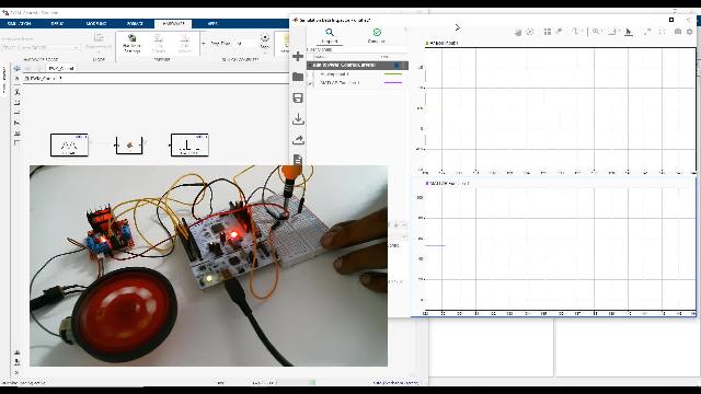
In the part two, we will continue working with the same model to understand how to use a PWM signal to adjust the brightness of an LED connected to the VW port. At the end of the video, we will use both these capabilities to adjust the brightness of an LED using the potentiometer. Also, we will use the same model to vary the speed of the DC motor using L298n motor driver, using the PWM signal.
Before we get started, make sure you have Matlab installed in your PC, along with Simulink and Simulink encoder support package for STMicroelectronics nucleo boards. If you want to learn more about how to install the Simulink encoder support package for STMicroelectronics nucleo codes, please refer the link in the description of this video.
You will need a potentiometer, a breadboard with few jumper wires, and a nucleo clipboard that is supported by the hardware support package to follow along. You can see the list of hardware supported by a particular support package in the Matlab documentation. I'll be using the NUCLEO-F401RE board in this video.
To get started, open Simulink, create a blank model, and save the model with the name of your choice. I'll be calling it ADC. Once you have saved the model, configure the model for the specific hardware configuration that we are going to use. To do this, click on the Modeling tab, select the Model settings, and under Hardware implementation pane, select the hardware of your choice. In my case, it's going to be the STM 32 NUCLEO-F401RE.
Then, under target hardware resources, you have to enter the composite of the hardware that has to be used for the connector your external mode.
To find the COM port of your hardware, go to Device Manager and under Ports, you can find the COM port of your hardware. In my case, it's COM4 for the nucleo board that I have. Enter this value, and click on Apply. To learn more about why we need these values to be entered, please watch the Working With Digital Inputs and Outputs On The STM32 using Simulink video mentioned in the description.
Now you will see that there is a new tab called Hardware with the selected hardware board. This shows that the model is ready with the hardware configuration. Let us add the ADC block from the Simulink encoder support package for estimated electronics nuclear. If you double click on the block, it will open the Block Parameters window where you can configure the block with various different parameters.
To get more information about each of these parameters specific to a block, click on the Help button. You'll be able to see the help page with all the details specific to a block. As you can see on the help page, if the measured voltage equals to the ground voltage, the block emits 0. And when it measures the analog reference voltage, which is 3.3 volts on the 401RE board, it emits 1.
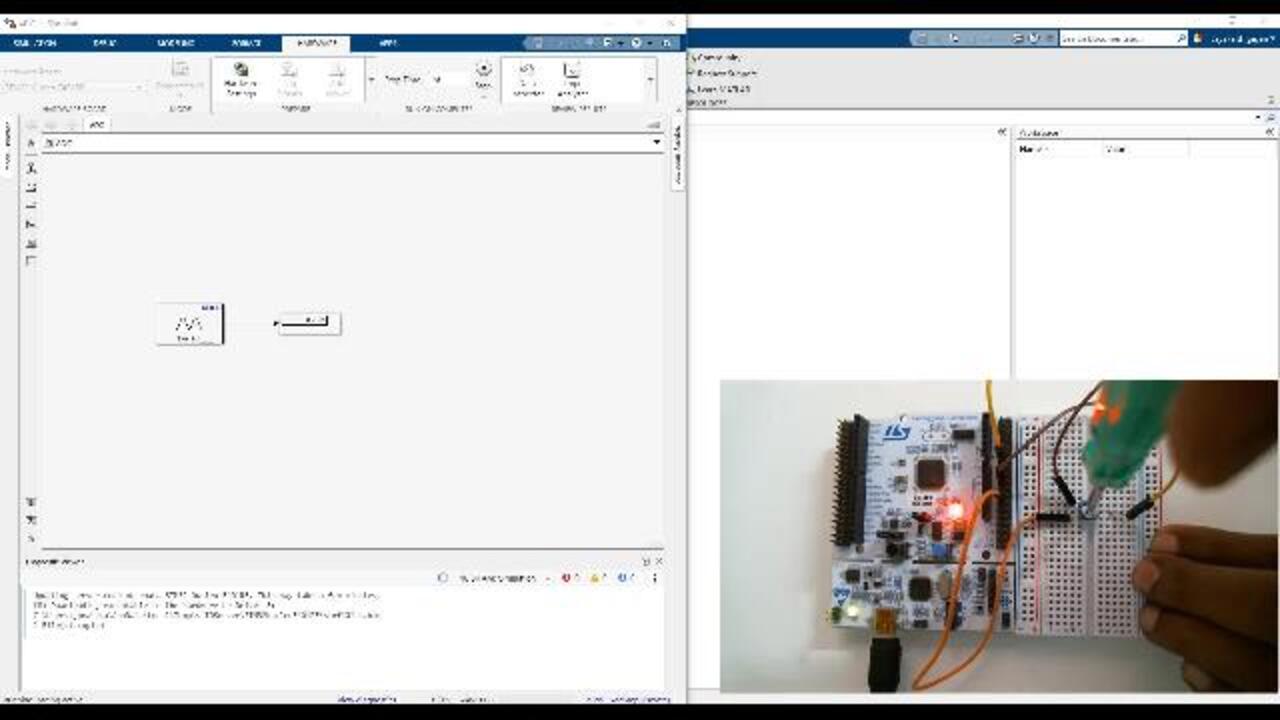
Say for example the measured voltage is 1.65, which is half of 3.3, the block will emit 0.5 as the value. Now that we understood how the block works, let's try it on the hardware. To do that, let's specify the pin configuration of the analog pin that we are going to use. You can click on the View Pin map to identify the pin name of the pin that you're going to use. In my case, it's going to be the analog port 0. Let me specify this value, and then click apply. As the next step, add the display block to read the output values of the block in real time.
Before we run the module on the hardware, let's wire the hardware with the potentiometer as per the circuit diagram. Once the module in the hardware setup is ready, run the module in the connected IO mode to see the real time action. To learn more about different modes of working with the hardware from Simulink, please watch the Working With Digital Inputs And Outputs On STM32 Using Simulink video mentioned in the description.
As the module runs, you will start reading the values from the analog input port which is displayed on the display block. You can also log the signal and visualize it in the simulation data inspector. Please read the documentation on the data inspector to learn more about it. As you can see, when I turn the potentiometer from 0 to 3.3 volt the values on the signal changes from 0 to 1.
With this, we come to the conclusion of part one of this video. In part two we'll continue working with the same model to adjust the brightness of an LED using the potentiometer, and also to vary the speed of the DC motor using the PW signal. Thank you for watching.
Related Products
Learn More


Select a Web Site
Choose a web site to get translated content where available and see local events and offers. Based on your location, we recommend that you select: United States.
You can also select a web site from the following list
Americas
- América Latina (Español)
- Canada (English)
- United States (English)
Europe
- Belgium (English)
- Denmark (English)
- Deutschland (Deutsch)
- España (Español)
- Finland (English)
- France (Français)
- Ireland (English)
- Italia (Italiano)
- Luxembourg (English)
- Netherlands (English)
- Norway (English)
- Österreich (Deutsch)
- Portugal (English)
- Sweden (English)
- Switzerland
- United Kingdom (English)