Model Description | MathWorks Minidrone Competition
From the series: MathWorks Minidrone Competition
Get details about the Simulink® model that needs to be used for the MathWorks Minidrone Competition and learn how to use the Simulink Support Package for Parrot® Minidrones.
Published: 21 Jun 2024
Hello, everyone. In this video, we will talk about the model we will use for the MathWorks Minidrone Competition. Before we begin, let us talk about the requirements to participate in the competition. One would need to install the latest release of MATLAB. Every team participating in the competition would get a complimentary license from us. We would request everyone to complete Simulink Onramp, which is a quick introduction to the basics of Simulink. And the next thing necessary will be the Simulink Support Package for Parrot Minidrones.
Now let's move to the Simulink Support Package for Parrot Minidrones. Where do we find this particular support package? You can get the support package from Add-Ons, Get Hardware Support Packages, and Simulink Support Package for PARROT Minidrones. And what does this hardware support package do? Using the hardware support package, we can deploy the algorithm that we have developed in Simulink directly onto the Parrot Minidrone hardware. For more details about installing the hardware support package, go through the webinar on programming drones using Simulink, whose link is provided in the description.
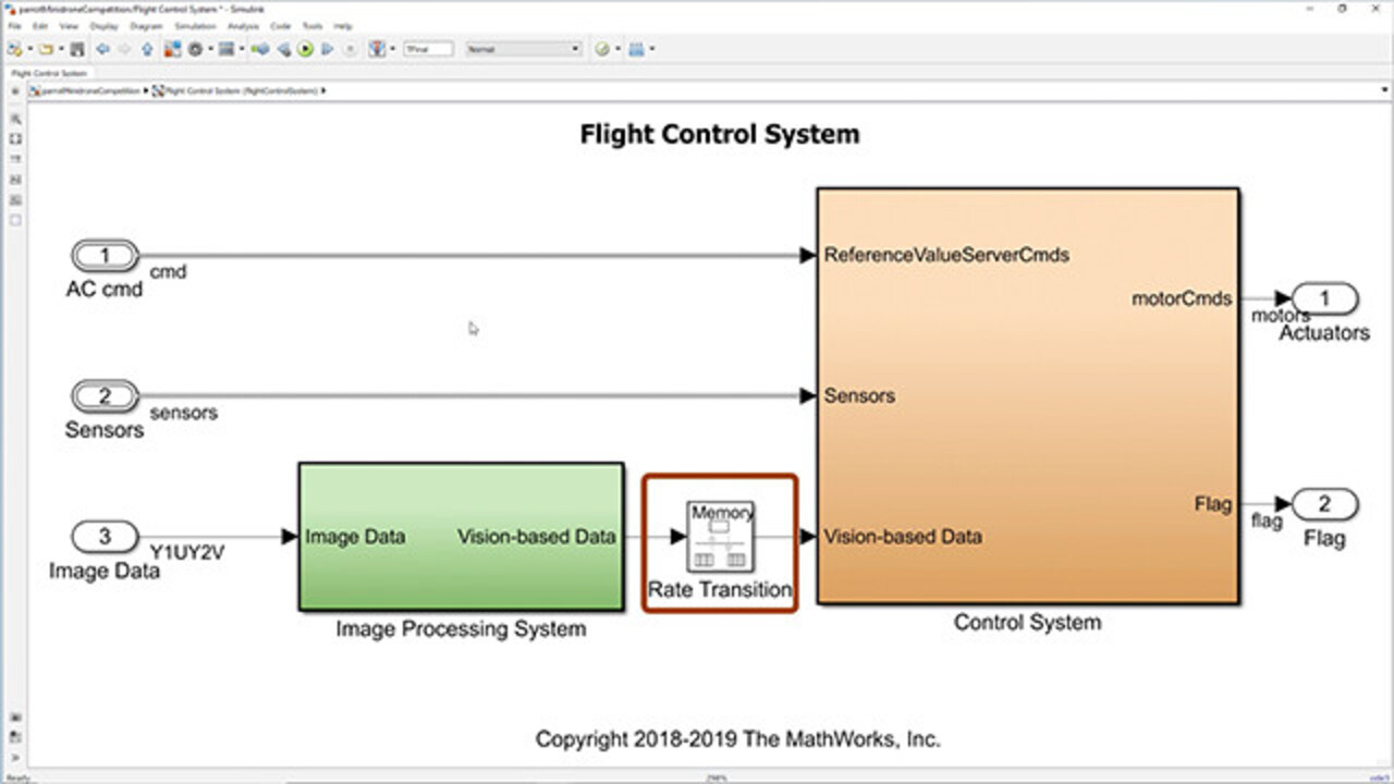
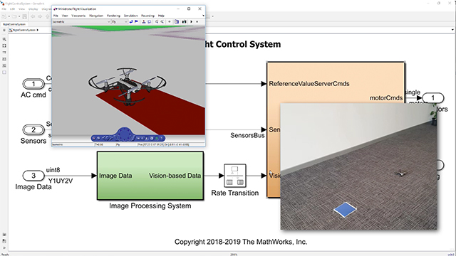
Now let us move to the model that we will use for the competition. Type parrotMinidroneCompetitionStart. This will open up a Simulink project that we will work on. And every time this command is typed, a new Simulink project is created. This is how the model looks like. It has a visualization in which we can view the drone's behavior. Now let us run the simulation using this Run button.
So this is the visualization, and this is the camera feed that we obtain from minidrone's downward-facing camera. Here the drone takes off, moves to the right until a blue-colored box is detected. The algorithm from the Flight Control System block is the one we will generate code for and then deploy onto the hardware.
Now let us explore the contents of this Flight Control System. The Flight Control System has two parts, the Image Processing System, and the other one is the Control System. Since the two systems operate at different sample times, we have a rate transition block between the Image Processing System and the Control System.
Let us see the Image Processing System. In the Image Processing System, we have modeled the logic for detecting blue color. We first get the image and convert it from the default YIUY2V format to RGB format. We can also convert this image into a YUV format image as well. Here we used a video viewer to view the RGB image that is obtained from the camera.
We then perform a small image processing algorithm on the image pixels and then find a parameter that would convey the dominance of blue in the image. In this case, we send a Boolean value, which is true if blue color is detected. This parameter is an input as vision-based data to the control system through the rate transition block.
Now let us look inside the Control System. For the competition, the subsystem the participants are expected to work on is the Path Planning block. The data from the Image Processing block is an input to this particular system. Let's navigate inside the Path Planning block. We have kept the value of x as 0 and the value of z as minus 1.1, which is height of 1.1 meters.
And since we have to move to the right, we will just change the value of y. We use the vision-based data that we have got from the Image Processing System as an indication of blue color detection. This takes a value of 1 if blue is detected. Otherwise, it takes a value 0. We latch this output to 1 from the first moment where the vision-based data takes the value 1. In the second part, we constantly keep incrementing y by a specific value until the input value is 1. And the value at the output is what we update in the position reference.
We can also use the estimated values which are obtained as an input from the state estimator. One thing to keep in mind is that whatever image processing algorithms are to be carried out on the hardware have to be present in the Image Processing System and the logic for navigation and control has to be in the Control System to ensure that you do not transfer an image or a section of an image as an input to the Control System. This is because the Control System operates at a rate faster than the Image Processing System.
Now, once we are done with designing our image processing algorithm and the path-planning logic, we will have to check that our model is code generation capable. To do this, there is a button in the Project Shortcuts called Generate Code. When we click on it, the code for the flight control system is generated. And when the code is built successfully, we see this particular sentence.
If you need any further information, please go to the documentation for Simulink Support Package for Parrot Minidrones. If you have any specific questions, feel free to ask us on MATLAB Answers with a tag of "MinidroneCompetition." And in case of any other queries, you can reach out to us at RoboticsArena@mathworks.com. See you all in the next video.


Select a Web Site
Choose a web site to get translated content where available and see local events and offers. Based on your location, we recommend that you select: United States.
You can also select a web site from the following list
Americas
- América Latina (Español)
- Canada (English)
- United States (English)
Europe
- Belgium (English)
- Denmark (English)
- Deutschland (Deutsch)
- España (Español)
- Finland (English)
- France (Français)
- Ireland (English)
- Italia (Italiano)
- Luxembourg (English)
- Netherlands (English)
- Norway (English)
- Österreich (Deutsch)
- Portugal (English)
- Sweden (English)
- Switzerland
- United Kingdom (English)