Vehicle Modeling Using Simulink
From the series: Improving Your Racecar Development
Join Ed Marquez and Christoph Hahn as they discuss Model-Based Design, Simulink® models and demos, and solvers. In the beginning of this video, you are introduced to Model-Based Design and equation-based modeling. Ed and Christoph then explain how to model vehicle dynamics and specific components using a power loss approach. While they offer a high-level overview, MATLAB and Simulink student lounge provides you with an in-depth explanation of battery modeling if you’re interested in learning more. The demos shown in this video reinforce the concepts learned and explain how to implement such models in the Simulink canvas. Last but not least, Ed and Christoph touch on the question of solver choice briefly. You can find detailed information about solver choice in the documentation.
Find the models used in this episode on MATLAB Central File Exchange.
Published: 11 Aug 2017
SPEAKER 1: Hello, everybody. You're watching the MATLAB and Simulink Racing Lounge. And in today's video, we are going to talk about vehicle modeling. To be a bit more precise, in the next four videos, we are going to talk about vehicle modeling, because that was a request that came from the community. You have asked for that.
Before starting, I'm super happy that Ed is on board. Hey, Ed.
SPEAKER 2: Hi, Christophe. How are you?
SPEAKER 1: I'm doing fine, how about you?
SPEAKER 2: I'm doing great. Thank you.
SPEAKER 1: Cool. As I said, we are going to talk about vehicle modeling. Today will the part one of a four video series. But before jumping into the content, could you introduce yourself briefly?
SPEAKER 2: Absolutely. My name is Ed [? Markus. ?] I'm an Application Support Engineer here at the MathWorks, and my background comes from automotive competition. So I'm pretty excited to be here.
SPEAKER 1: Cool, Ed. So let's know our viewers what we are planning to do in the next four videos and especially in that video.
SPEAKER 2: Absolutely, Christophe. As you mentioned, we have a series of videos where we're going to cover different modeling techniques for automotive systems. So today, we're going to start with the first part, which is just Simulink. And we're going to cover an equation-based approach.
Then, the other parts are going to also include different platforms. For example, the Powertrain Blockset. That's a relatively new tool box that we released with our 2016b. This is a different approach to Simulink. This is data driven as opposed to equation based.
Then, in the third and fourth part, we're going to cover Simscape products, where we actually enter into the physical modeling domain. And in the end with Simscape Multibody, we're actually going to be able to do some 3D modeling and visualization of our systems.
SPEAKER 1: That sounds great.
SPEAKER 2: For today, it's just Simulink, so stay focused and relaxed. And what I want to do is also introduce a demo to show our audience what we're going to end up with after today's session. So today, what we're going to see is how to create a vehicle system in Simulink. In this case, I have a battery electric vehicle. But you can also create a conventional combustion engine system.
And a model like this can give us a lot of detailed information about a motor operation, battery operation, and also what is going on in the drive line for a certain input. In this case, the inputs that I'm working with are EPA certification drive cycles. And then, I can determine how big my battery needs to be, or how powerful my motor needs to be, and I can also generate some information for visualization, like a torque envelope for the motor and also how my state of charge the battery changes over that drive cycle.
So if you stay tuned, that's kind of what we're going to end up with today.
SPEAKER 1: Great. So give us 25 or 30 minutes of your time, and we will ensure that you can set up a vehicle model right afterwards. Another comment before I heading over again to Ed, we will put all models, everything we display here in these videos, on File Exchange. So no need to rush and rebuild any models. We put everything-- we make everything available for you Fie Exchange.
And Ed, why should people do vehicle modeling in Simulink?
SPEAKER 2: Well, I think vehicle modeling is very important. But first, again, we're going to cover that motivation in more detail in the next slide. We're going to go over the demos, and then, I'm going to throw in a bonus on solvers. Solvers are very important when you're doing modeling in Simulink, whether it's a spaceship or a vehicle, the Solver's choice is very important for your modeling efforts.
SPEAKER 1: Exactly. I 100% agree. I have some models that were great but that were running slowly, mainly because the solver wasn't chosen appropriately. So thanks for putting that in the agenda. And I think the next point is, what are the key benefits of modeling? What are the key benefits of model based design?
SPEAKER 2: Absolutely. So I'll start with the conventional design process, what we've seen in the past. And what you've seen is that engineers start with requirements for the system in the form of a document. Then, a very expensive prototype is created, maybe driven in the snow and crashed.
Then, some data collection happens for those tests. Then, the engineers figure out what went wrong, whether it's a software or hardware issue. If it's a software issue, they create a patch. And then, they have to go back and test the prototype again. And you can see that this can be very expensive and very time consuming.
So the new approach that includes modeling is called model-based design, where you base the design of your system on different models and you can simulate on a computer and also test it with hardware. So the new approach, actually, you start with the same documented requirements. Then, the engineer actually comes up with a system and creates some models with mathematical representations for that system. And then, that is simulated on a computer and also can be simulated on hardware platforms.
SPEAKER 1: Cool, Ed. Thanks a lot for visualizing that for us. That's very appealing, and I guess it's convincing. Let us know if you think otherwise, but I found that pretty convincing. And can we summarize somehow the key benefits of model-based design?
SPEAKER 2: Absolutely. So if the system actually meets those requirements, then you can start creating your prototypes. And you can see that this is a more time efficient and cost effective process. And so to summarize the benefits, you can actually simulate different powertrain architectures and different component sizes very quickly in a very time efficient manner.
Then, you can also run very fast simulations. I mean, running a simulation is much faster than creating an expensive prototype and then testing it. And finally, these models can give you enough detail so that as an engineer, you can also analyze the environmental impact but also the performance aspect of your vehicle system.
SPEAKER 1: And that's particularly important in early stages of your design and in the planning phase, where you want to know how much torque your car needs and what of fuel consumption you can expect. So this may even happen before you even have parts of a prototype at hand. Benefit early from modeling, right?
SPEAKER 2: That is right.
SPEAKER 1: Cool.
SPEAKER 2: All right, so the first platform that we're going to cover today is Simulink. And again, one of the things that I like about Simulink is that it is the quasi standard for control design in academia and industry. So that makes it very accessible.
And it's also the baseline for a lot of different tools that we provide, for example, Simscape, Simscape Multibody, the Powertrain Blockset, and more. And Simulink also provides an equation-based approach for modeling, and it also supports code generation. So if you're interested in testing your models in hardware, Simulink also supports that capability with a few other toolboxes.
SPEAKER 1: Cool. When you say code generation, we mean automated code generation directly from Simulink. So you could put your controllers, for example, directly onto your ECU so that they are running there and not on your desktop computer anymore. This is available from the Simulink platform, but all the other attach tools, like Powertrain Blockset and Simscale as well.
SPEAKER 2: That is correct. l Excellent. And Simulink is also a great choice if you want to get started with vehicle modeling. Or if you're an advanced user, then Simulink is great, too. And if you're looking for simplicity and speed in your models, Simulink is definitely a great choice as well.
And again, it provides an equation-based approach. So I would suggest everyone to check out this link, where we have our material and documentation on how to get started with Simulink if you don't have that type of background.
SPEAKER 1: Excellent. And I think now, we are going to talk a bit about that equation-based approach that we're using in Simulink. And we want to set up a vehicle model in that episode, and I think this is where we are going to start now.
SPEAKER 2: Exactly. So to begin with, we're going to set up a glider model that represents the vehicle dynamics of the system. So in this free body diagram, what we have is a vehicle, and we're representing the dynamics of that vehicle system as a point mass.
So the important thing to remember about this is that the tractive force has to overcome all of the resistive forces, and that can be shown in this equation here on the right. So the track to force needs to overcome the aerodynamic drag, the inertial resistance, the grade force if you're on a plane or incline, and also the rolling resistance force.
And again, the input for this model would be a drive cycle, a certification drive cycle. But these models that we're going to provide can be customized to work with, let's say, a lag time, or any other input that you would desire.
SPEAKER 1: That's perfect. A quick comment on this, and you call it glider model. A few people out there in the community might have heard of a single point, or a single mass approach. This is exactly what we are talking about.
SPEAKER 2: Correct. Yes, it is exactly the same thing. So without further ado, I can introduce how to create this simple model in Simulink. So let's go and take a look at that.
SPEAKER 1: Yes, please. Looking forward to that.
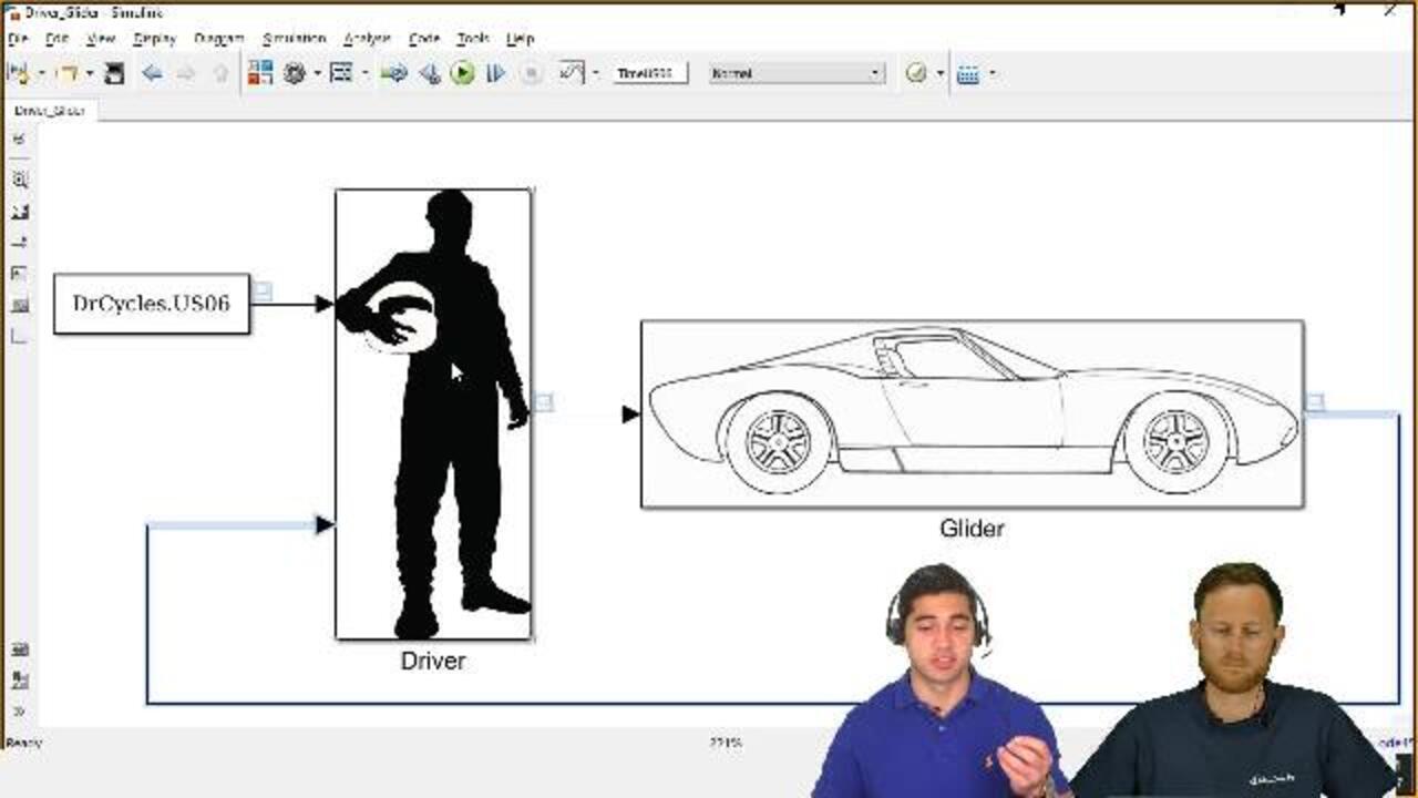
SPEAKER 2: Absolutely. So here is the way that you would put this together in Simulink. We start with the glider model representing the vehicle dynamics, and we have a simple PID controller representing a driver system. So the driver system, what it's doing is taking the reference speed from the EPA drive cycle. It's comparing it to the vehicle speed that we're measuring from the model, and based on the arrow, that is determining a tractive force command. That's what comes into the glider model, or the vehicle dynamics.
So what we do here in this subsystem of the vehicle glider, we take that tractive force, and we do a summation of forces by this equation here. So what we are calculating is the inertial force. Because we take a tractive force, and we subtract all on the resistance forces. We calculate an inertial force, and we divide by the inertial mass factor.
Then, that gives us the acceleration, and we can integrate that once and twice to also get the velocity and displacement of the vehicle.
SPEAKER 1: And at the end, it's mainly modeling equations. So we've put down the equations. We touched that very briefly. We've also put all the reference to the slides. In case you need to refresh your memory, we've put all the references. Just check all the books again.
And setting up equations in Simulink is fairly easy. We won't do a deep dive here as well, but we have a Racing Lounge episode which is called Principles of Control Design, where we talk in depth about how to take equations or even differential equations and create a Simulink model from that. This is what Ed has done here for us. And actually, it's surprising how low the number of blocks is, and this is our first vehicle model, right?
SPEAKER 2: Absolutely. Yep, and this a very simple model but again, can give us a lot of information, a lot of high level information. So once you have the velocity displacement of the vehicle, you can actually determine how much power you need to propel that vehicle and how much energy goes into braking for that drive cycle input that you provided.
So what I'm doing here is multiplying the tractive force times the velocity to get power. Then, I can integrate that to get the energy. And I can separate that into propelling energy and also braking energy. So again, very simple model that can give us a lot of high level information. So for instance, how much tractive force and power I would need to move a vehicle of certain weight for a given drive cycle.
SPEAKER 1: That's perfect. Could we have a brief look at the driver? I assume that's a controller, but let's give our viewers a chance to see what is happening here.
SPEAKER 2: Absolutely. You're right. This is a PID controller. Again, what I'm doing is calculating the error between the speed reference and also what we're measuring from the vehicle model. Once we have that error, we come to a PID that I decided to implement. We could have used a PID block, but that's one of the beautiful things about Simulink. You can implement and model different things with different approaches, so there's a lot of flexibility when it comes to that.
SPEAKER 1: That's great. And as we are lecturing here a bit, it's good to not only use the PID block but to show the background. That's great.
SPEAKER 2: Excellent. That's the model. And then, we can actually run it. It runs relatively fast. It run in less than a second. So what we can look at in this viewer here here is the response of the model and also the reference input that we provided.
So here, we can say, I have two lines. I have a yellow line in the background and also the blue one. So the yellow line is actually the speed reference that we provided, that EPA certification drive cycle. Now, the blue line is the response of my model.
So by inspection, we can definitely tell that we're meeting that drive cycle, and the tractive force and power that we're using for that mass is just adequate to meet that drive cycle.
SPEAKER 1: Cool. A single comment at that point. Some teams from the community that intend to build a race car have already a pretty useful tool for that model, because they can run parameter studies and see whether they need a bit more torque or a bit less weight to achieve certain improvements on their lap time. So this could be already a first and simple lap time simulator.
SPEAKER 2: Now, we'd like to talk about a different modeling approach. This modeling approach is called power losses. And what we're doing here is looking at the power flow for the component. So we're modeling the component with a power input, and we're also interested in the power output to that. But we recognize that there are some losses in power associated with the operation of that component.
So one of the advantages of this method is that it's relatively easy to understand, and it is also well documented. So I've provided a reference if you're interested in learning more about that. But in this case, they losses of a component can simply be characterized by a quadratic equation. And some of these coefficients, c0, c1, and c2, can also be characterized from testing or from initial parameterization in your model.
So how would we apply that power loss modeling to describe a component, like a motor or a battery? As I mentioned, we start with the power input, but we're interested in the power output and that we have some power losses associated to that. So for a motor, we understand that the power output is the mechanical power that comes from the shaft. So that is the torque of the motor times the rotational speed.
The losses, we're going to characterize with this equation, which is dependent on the motor torque but also the rotational speed and some parameters that we have in this table. And the power input we know is the power output plus the power losses. So we can calculate that this way.
Another advantage of the power loss modeling approach is that it's pretty easy to implement for components that have bi-directional operations. So for example, a motor can act to propel as a motor. It can also capture energy from regen braking, acting as a generator.
All I have to do is just use these two different equations by reversing the definition of the efficiency, and then that is taken care of. Excellent. So that was the motor modeling approach. Now, we're going to talk about how to model a battery. And what we're doing here is we're just modeling the battery with an internal resistance.
So Christophe, I want to highlight that this is different from the equivalence circuit approach, because we're not modeling the parallel resistive and capacitive components that the equivalent approach actually has. So this is slightly simpler. And what we're doing, again, is modeling an internal resistance and a loading resistance for the battery.
SPEAKER 1: Right. And this approach is pretty much independent of the battery chemistry, but nonetheless, it's super helpful to set up a simple vehicle model. If you want to get more involved, I suggest you check out the Racing Lounge episode about battery modeling. And it's fairly easy to flip the battery models.
But I really like the approach of going really simple. And this is mainly about predicting state of charge, right?
SPEAKER 2: Absolutely, just understanding how big a battery needs to be to meet a certain drive cycle. And again, one of the things that I like is it's simple enough that it doesn't really take into account the battery chemistry. It takes more the high level aspects of operation.
SPEAKER 1: Cool.
SPEAKER 2: So here, we start with an ideal power, which is what we have in the battery. And what we're worried about is the power losses that we may have in the battery. And again, that's just the battery current times the power losses.
And I'm also going to show how to implement these equations in Simulink. So we can determine our power losses based on that internal resistance, and then we know the ideal power in the battery from the open circuit voltage of the battery. So it's a relatively simple approach, and we can describe also the state of charge with this equation here.
SPEAKER 1: So I think there are a few pieces missing, the driveline, right?
SPEAKER 2: Yeah, so that's the last piece that we have to put together on a battery electric vehicle. And the driveline is pretty simple. The driveline, what it has to do is just transmit the torque from the motor to that glider model. So the inputs for that would be the motor torque, a braking force that comes from our driver subsystem, and also the vehicle speed, and then the driveline outputs are the tractive force that we're sending to the glider, and then the motor speed. That's something that is calculated and fed back to the motor.
And we can calculate the tractive force from this equation right here. We have the torque that comes from the motor minus a constant torque loss that we're associating that driveline with. Then, we have the gear multiplication, the torque multiplication that happens in the final drive. We divide that by the wheel radius to get a tractive force.
And then, we subtract the braking force from that. And that way, we get a net tractive force that we can send to our glider model.
SPEAKER 1: Makes sense to me. Cool. Right, we have done our homework, and we put all the references. If you feel you need to check that out again, go ahead. And I think now, I would be super curious to see that implemented in some modeling. Is it super tricky, or how did you do it?
SPEAKER 2: Absolutely not. This is actually relatively easy to implement.
SPEAKER 1: OK, nice.
SPEAKER 2: So here, what we're seeing, again, is a battery electric vehicle. So we have the battery, the motor, the driveline, and also the glider with the driver system that we saw before. So again, this component, the driver, and also the glider do not change. These are the same ones that we developed before.
So here, what we're adding is just a braking system to process the braking force command that comes from the driver. What we're really interested here is the motor. So in the motor, if we go in there, all I'm doing is implementing these equations.
So the first step is to take the accelerator pedal position that comes from the driver and find the torque envelope for operation of the motor. So that is what this first subsystem is doing here. Then, I can determine what is my maximum torque for operation, and that's what I'm implementing with these equations.
And I'm doing the same thing for regenerative operation. So that way, I have a torque envelope for propelling and braking with the motor. So once I determine the positive torque and the regenerative torque, I add up those two. And that way, I can get a net motor torque.
SPEAKER 1: And then, it's simply applying the loss model and with that we just introduced.
SPEAKER 2: Excellent. Yeah, so in this motor losses subsystem, all I'm doing is implementing that equation that we saw for the motor loss's equation.
SPEAKER 1: And what you did here is actually great. You kept the model itself on the white Simulink canvas, and then you highlighted what you added to the model additionally for analysis and results. So this is not required from the theory point of view. This is just for us to make life easier to visualize some things to do some post-processing.
But actually have a look. It doesn't require a lot of Simulink blocks to set up a vehicle model, including losses, right?
SPEAKER 2: Exactly. So, again, what I'm doing in this portion of the model is determining the power input, the power output, and also the energy input and output that go to the motor. And I can use that for post-processing to get information from that model.
Excellent. So if we follow this connection here, we go to the battery. And the reason why the motor and the battery are connected is because the power input to the motor is actually the power output to the battery. So once we bring that in here to this port, and we also associate it with an accessory load.
So let's say the power windows, or the AC in the car, so we add that load. Then, that is the power output to the battery. And what we're doing here in this equation is just calculating the current. Or in this subsystem, we're calculating this equation right here.
So this subsystem actually gives me the open circuit voltage, the battery current, and also the internal resistance of the battery. So with those three pieces of information, I can actually calculate my state of charge, the battery power losses, the energy losses, and also the power of the terminal of the battery, so the power output. And I'm doing that by just implementing these equations here at the bottom with those three pieces of information.
So just to go over the power battery losses, that's what we're mainly interested, that is, we're modeling that as i squared r losses. So with these two pieces of information, I can determine how much I am losing in my battery because of internal resistance.
SPEAKER 1: These models are beautiful. Nicely documented. And again, the hint, find them on File Exchange. We will provide it for you.
SPEAKER 2: Absolutely. Absolutely. And so a big other piece of information for the batteries is the state of charge. And here's the equation, and we've implemented that nicely here in this top signal.
Finally, the driveline that takes in input, again, from the motor, if we remember, the motor torque, the brake command, and also the vehicle speed. And so here are the inputs to the left. And what I'm doing is adding that constant torque loss if my vehicle speed is not zero. Then, I'm adding that to the motor torque.
A loss term is negative, so I'm adding those two to get the actual torque after the losses. And then, I multiply that by the gear ratio divided by the wheel radius to get a tractive force. And then, to that tractive force, I actually subtract the friction braking force that comes from the braking system. That actually gives me a net tractive force, and that's what actually goes through the glider.
And again, I associated everything here for information and for later analysis in this top portion. So we can also determine power losses and energy losses and things like that.
SPEAKER 1: Awesome. Cool. I think this is about the highlights of the model. We went through everything. I think, now, let's give that model a chance to show what it can do.
SPEAKER 2: Right, so it runs relatively quickly. It ran as I was saying that. And the drive cycle is 600 seconds long. And we saw that the model actually runs in less than a second. So after I run it, I auto generated these three different plots to visualize some information.
So the first one that I want to show is the state of charge. And we can see that I started at about 95%, and it went all the way down to 25%. So that tells me that the battery is big enough to meet that drive cycle. So if I were a user here, I would consider maybe making the battery larger based on the information that I can get from this model.
SPEAKER 1: Yup. That makes sense.
SPEAKER 2: Another cool thing is that you can actually visualize region braking events, so you can see the state of charge going up. And that means that the battery is also being charged from braking.
SPEAKER 1: Cool. I'm pretty sure that the guys in charge of vehicle concept design will see the beauty behind these plots. And what else do we get as outputs? So we get some envelopes. What do these curves tell us?
SPEAKER 2: OK, so the one that I have here on the left is the motor torque envelope. So the information that I can get from that is all the points that my motor is operating at at different times. So you see a high density of points here. That tells me that this motor is operating a lot in this region during the US06 drive cycle as the drive cycle implemented here.
And that tells me that there are some points where the motor actually goes to its peak operation. So you can see the 500 newton meters of torque, and then here, we get a nice drop in torque for the constant power region.
So you can get good information from this. And you can also make decisions from this kind of information. You can say, hey, maybe my motor needs to be larger. Maybe my motor meets this drive cycle perfectly, so I can make it actually smaller.
SPEAKER 1: Nice. Perfect. Yeah, I think this is super helpful. The model we are running is independent of your actual hardware. And by using these plots and running these simulations, you can see whether your actual motors or battery would fit your needs. That's excellent.
I have now a question, which I think is not super easy to answer. Imagine you're a team. You set up that vehicle, that vehicle model in particular. How would you calibrate it, or how would you validate it, or how would you make sure that this is in alignment with the actual hardware you want to put into your race car?
SPEAKER 2: That is actually a great question, Christophe. And that's more of a process. It's a workflow on how to work with these models and get good information from it. So what I can recommend is definitely starting maybe with the defaults that we're providing, the default values. And then, you want the parameterize your model to meet your requirements.
So for example, if it's meeting a drive cycle or a certain lag time, start there, tweaking those parameters. And then, after that, you can progress to obtaining test data to actually calibrate this model. So once you move on to more advanced stages of your project, you can test your actual vehicles, get some data, and actually feed it to this model to match your real life data.
SPEAKER 1: And correct me if I'm wrong, I would start with also subcomponent testing. So what I would do is I would put some load on my battery and make sure that I parametetize the subcomponents first, and then bringing all that data together into the model. Is that a meaningful approach?
SPEAKER 2: That is definitely meaningful, because you want to make sure that all the little paths that keep your model together actually perform and behave as you expect. Right here, this last plot that we have is just the battery power versus vehicle speed. The important thing to understand is that there are positive power points and also negative power points.
So we can see that there is power being drawn and put back in the battery through region braking. So that's pretty useful to have from your model.
SPEAKER 1: Extra nice. Extra nice. We really hope that this was helpful to you. And I think at that point, Ed, we can wrap that video up and, well, summarize the key takeaways.
SPEAKER 2: Excellent. So the last thing is, Simulink, again, is an equation-based approach. It offers simplicity and speed. And the users have to know the equations of the systems that they're working with.
SPEAKER 1: The good thing, however, about the equations that you need to know, a lot of that stuff is documented in standard literature about vehicle dynamics, about vehicle modeling. And so you will find more than enough approaches, and I'm pretty sure there are dozens of approaches how to model power loss.
So we just took one of the approaches documented in literature, and that's your freedom. You can model whatever you want. Just check out the literature and make sure you take something appropriate.
SPEAKER 2: Then, the big thing about Simulink, also, it supports automatic code generation for hardware testing and also deployment. And the last thing that I want to cover is just a very quick overview on solvers, because solvers are critical when you're trying to do some modeling in Simulink.
SPEAKER 1: And at that point, we are really oversimplifying stuff. Choosing the right solver can be tricky, and we will address that point as we go along. But I think at that point, it's about making you sensible that solver choice is key. Check out our documentation about that.
But again, I'm handing it over to Ed to do a high level summary about solvers, because solvers are important.
SPEAKER 2: I think that is a great suggestion going to our documentation, because there is a lot of detail and information when it comes to solvers. But here is the very high level characterization that I can provide. And the first thing to know is that we have variable-step solvers but also fixed-step solvers.
Variable-step solvers can be non-stiff, meaning that they solve non-stiff systems, and they can also be stiff, which are more made for Simscape models, but we're going to cover that in the future. The fixed-step solvers are more suited for different models to generate code from.
And they're for distinguishing criteria when it comes to solvers as well. We cover one, the step size, whether it's fixed or variable. There's also the state updates. A model can have only discrete states or continuous states. And also, the integration approach. It can be explicit or implicit. So some solvers may need to solve the whole system in a single time step, whereas the explicit solvers may not need to solve the whole system in a single time step.
And finally, the order of integration. So that can be fixed or variable, and you can get that type of information from the solver name. So if the solver has one number in the name, that actually means it represents the order of integration. So that tells you the accuracy in the solution that Simulink will try to find the results to.
If there are two numbers in the solver name, then that is a variable integration order, and Simulink will find the best solution between the first order and fifth order solution, in this case. And you can refer to this criteria right here to better understand what information you can get from the name of the solver. But we're going to provide some more information on solvers in the future, hopefully.
SPEAKER 1: We will. We will, Ed. Thanks a lot. Thanks a lot for presenting stuff about Simulink. I found it super convincing, and I'm already looking forward to the next videos we're going to do.
Let me take the opportunity to close that video for you guys. We are super interested in your feedback. Please send us an email if you want to send us a personal feedback.
If you think it should be public, please join our Facebook group and share your feedback there. If you want to check out more reviews of the Racing Lounge, I think we are beyond 50 now, go to mathworks.com/racinglounge.
And if you are a student team, and if you are competing in automotive competitions, make sure that you check out our software offers for student competition teams. And if you do use our software, we would be delighted if you put our logo, the network's logo on your car, or on your reports.
Ed, I think we can have a pretty brief goodbye. Let me thank you, but we will meet again.
SPEAKER 2: Bye bye.
SPEAKER 1: See you guys.
Related Products
Learn More


Select a Web Site
Choose a web site to get translated content where available and see local events and offers. Based on your location, we recommend that you select: United States.
You can also select a web site from the following list
Americas
- América Latina (Español)
- Canada (English)
- United States (English)
Europe
- Belgium (English)
- Denmark (English)
- Deutschland (Deutsch)
- España (Español)
- Finland (English)
- France (Français)
- Ireland (English)
- Italia (Italiano)
- Luxembourg (English)
- Netherlands (English)
- Norway (English)
- Österreich (Deutsch)
- Portugal (English)
- Sweden (English)
- Switzerland
- United Kingdom (English)