Design and Simulation of Autonomous Surface Vessels | MATLAB Day for Marine Robotics & Autonomous Systems, Part 4
From the series: MATLAB Day for Marine Robotics & Autonomous Systems
Martin Luo, Application Engineer at MathWorks
We will demonstrate how MATLAB® and Simulink® can help design, model, and simulate ASVs and scenarios. You will see:
- Approaches for modeling and simulating ASV dynamics and electrical systems
- Simulation environments for simulating synthesized sensor data such as Unity®, Unreal Engine®, and Cuboid
- The development of autonomous algorithms, including perception, planning, and collision avoidance
Published: 23 Aug 2022
So hello, everyone. My name is Martin. And I'm an engineer from MathWorks Sweden. So today I'm going to give you an overview of what MathWorks offer for designing and simulating the ASV. With respect to time, let's jump directly.
There are many, many challenges for developing and ASV. One of them is that ASV should be able to avoid the obstacles in these heavy traffics. Another challenge is that usually developing the ASV contains a lot of functional pieces.
How can we kind of test this or verify these functional pieces before we deploy it? Or they test it with the hardware. So this is a challenge.
How can we address these challenges instead? We should have a digital team that includes both the ASV, as well as the scenarios. This is our implementation, as an example, that we have implemented into Simulink.
From the right-hand side, we have the vessel platform, as well as the payload and the involvement module. Moving to the left, we have the guidance control and navigation module. Which we can regard it as the automation of our system.
Moving to the left, we have the situational awareness module, as well as the planning module. We regard it as the autonomy system. Of course, in order to feed the sensor data into the autonomy module, we should have these scenarios as well, to kind of generate the synthesize sensor data.
Last but not least, we also have the human machine interface that we can kind of simulate the human machine operations for remote control. So this is the high-level overview of the digital twin, our architecture in Simulink. Then in the following session I'm going to give you some more details in each of these module. So let's get started on the vessel platform.
I would like to take this opportunity to introduce you the configurations of the ASV that we implemented. There are a couple of sensors. First of all, we have four camera sensors on the front, back, port, and the starboard side.
Next, we have a LiDAR sensor, as well as the IMU and GPS sensor. And naturally, we have two propellers, with the electrical motors. This is our configuration of the vessel platform.
We have the Simulink models for this vessel platform. This is a top model of this vessel platform in Simulink. From this screenshot, as you can see, we have the first model, containing these coefficients and these are thrust coefficients for the propellers.
We also have the waves and the cross flow model, as well as the hydrodynamics and hydrostatic models. All these are models. Under the hood, they are the coefficients from the experimental data.
We also have sum of the forces and moments that add all these forces and moments together, and feed it into the sixth degree of freedom equations of motion. We also need to feed the inertias, as well as the initial conditions into the 6DOF model.
This is a very high-level overview of the vessel platform in the Simulink model. Also, I think it would be good to know that Professor Thor Fossen, from NTU, he has this marine system simulator that's shared from the MathWorks MATLAB Central File Exchange, that you are free to download.
From this marine system simulator, it contains sets of libraries. You know, including ASVs, including AUVs, as well. Here, he also offer a couple of examples.
Let's say this ASV, and also include the control and the guidance, as a complete example. All right. Another way for modeling the vessel platform is to use Simscape. The Simscape product family enables you to model the vessel platform as a physical component, instead of writing the equations of motion.
So here is the example that we use some Simscape Multibody for simulating the payloads. So if you look at this animation, we can see that, let's say if the payloads that drops in on the ASV, so you will see how are the response of the ASV. So this is only one example of how to use the Simscape model body for modeling the payloads, and as well as the dynamics.
As you can see, there are also other Simscape model families, for modeling other or physical component as well. For example, here we use the Simscape electrical and the Simscape Driveline for modeling the actuators and the batteries.
For example, we have this battery model from Simscape electrical. And we also have the actuator model. As well as the motor model coming from a Simscape Driveline.
With that said, the Simscape, as well as the Simulink platform, enables you to model the vessel platform from hydrodynamics, hydrostatics. You know, currents and cross flows and this stuff, as well as the system components modules, such as the batteries, actuators, and motors.
This is all about the vessel platform that I'm going to show you today. So if we move on to the next model, the navigation. Here the navigation is all about how to estimate the vessel states using the traditional sensor, such as IMU and GPS.
Here shows the animations of how we utilize these sensor-fishing algorithms for our estimating the orientation and position using the IMU and the IMU and GPS. Also in math in Simulink, we offer a couple or virtual sensor models, such as IMU and GPS. And INS as well.
We also offer a bunch of sensor fusion filters. Let's say, of the AHRS for our orientation estimation. We also offer the INS filter for our sensor fusion by using, let's say, the IMU, the GPS, as well as the accelerometer, gyroscope, et cetera.
This is something that we offer for sensor fusion. But not only we offer the virtual sensors as well as the filter, but we also offer the automatic tuning features. Meaning that with these automatic tuning feature, it enables you to automatically fine tune the parameters in the filter. This will save you a significant amount of time. All right, let's move on to the planning module.
So before we talk about how we do the planning in Simulink and MATLAB, so I'd like to take this opportunity to introduce one of these simulation environments in our MATLAB in Simulink, which we call a cuboid. With Cuboid, you can kind of create these scenarios quick and easy.
Also with the Method function, as well as the Simulink blocks that we provide, it also allows you to co simulate between cuboid and your mother algorithm or the Simulink blocks. Also, we offer this scenario on our app, which allows you to design your design scenarios interactively in this app. In this app we have this Scenario Editor and the Scenario Viewer, which allows you to edit the scenarios.
We also have the Scenes, that you can add the scenes. As well as the Vessel Platform. We also offer a bunch of virtual sensors that you can kind of drag and drop and add it on the vessels.
On the left-hand side, yeah, so one more thing is that you can also perform simulations from this app. On the left-hand side, we have the Property Editor, which allows you to edit, change the parameters for each object. Lastly, we have the Actor List, that show all the object that we have added.
All right. Here is a recorded video, showing how we can create these scenes and scenarios in this app. First of all, we are going to add the ego vessel, from CAD file.
We have a CAD file for our ego vessel. Then we add it. We changed the color from the Property Editor.
We also changed, let's say, the orientations. And of the matches, just to make it looks correct. Next I'm going to add a LiDAR sensor there.
Now I select LiDAR sensor, I'm going to select the position, that I'm going to install on top of the vessel. Right. And on the left-hand side, we also have seen a bunch of parameters for the LiDAR. In the same workflow, we're going to add a couple of non-ego vessels from the CAD file.
The same workflow, we specify the CAD file. We change the color and the name and the field, you know, properties. Here we have all the non-ego vessels. Next we are going to add the scene.
Here we have the CAD model, of from the real-world scene, which is London, in this case. This CAD model is from Google map, anyway. Now we have added a scene.
Then we can, from this scenario viewer, we can zoom in and zoom out, and rotate and pan, and to adjust the viewpoints. And next we're going to add the waypoints, so to specify the scenario, right? So if I just drag and drop the waypoint, so you can kind of-- so as you can see, it is fairly easy.
And with the trajectory tables, you can specify the velocity profiles. Such as the ground speed. And so this applies for all the ego and non-ego vessels. All right.
After that, we can run simulations. We can see the results are right away. If we click the Run button, then you can see the vessel is moving, following the trajectories that we just defined.
This is a very quick video on showing how you can create the scenes and scenarios in Cuboid. In the following section, I'm going to show you how to use this Cuboid for planning. Besides that, Cuboid also offers a bunch of different virtual sensors. Such as LiDAR, Radar, and ultrasonic. In Simulink, we also offer GPS, IMU, INS, accelerometer, and gyroscope, and more sensors.
Regarding behavior planning. This is the first topic of our planning. It's a behavior planning.
In this case, we use stateflow for defining the state machines and the state and transition conditions. Here, as an example just to illustrate the workflow, we have defined three states of Free Operation mode.
One is Idle. Second one is Waypoint Following mode. And the third one is Collision Avoidance mode. In Cuboid, we have graded these scenarios. Then we can run a simulation.
Here we can see that here it detect the collisions. Then they will transition to the Collision Avoidance mode. Then when the risk has gone, it would transition back to the Waypoint Follow mode, as we designed from this stateflow chart.
This is about behavior planning. And another one about planning is Collision Avoidance. Here we have two different approaches for Collision Avoidance.
One is local re-planning. Let's say these are a trajectory, we will pass through the-- let's say the bridge, as the obstacle. Right? So here, we use, or we showcase the vector field histogram for avoiding these static collisions. And another way for avoid the collisions is we call the policy-based planning.
Here we have implemented a couple of scenarios, following the COLREGs rules. OK, so I will give you some more details. Regarding the vector field histogram for local re-planning.
First of all, we have the virtual sensors. Either from the LiDAR sensor, getting the 3D point clouds. Or the range sensor, getting the 2D point clouds, right? Anyway, it's the point cloud.
Then we feed this into the vector field histogram algorithm, or the model. Then this vector field histogram model will generate the obstacle-free steering angle to avoid the obstacles. This vector field histogram functions is offered by both MATLAB and Simulink. So you can just drag and drop and use this MATLAB or Simulink block to try out these full collision avoidance.
This is one. Another one is the COLREGs Rules implementation. This shows a simple example, that two vessels, they collide. According to the COLREG rule number 15, the crossing situation, the orange vessel on the bottom side should give way.
It's because, what our COLREGs rule number 15 tells us is that when these two vessels are crossing with each other, the vessel which has the other one on its own starboard side shall keep out of the way. So this is how we kind of implement this, as an action on the ego vessel, to ensure that it give way. Of course, it can also either give by turning right, to give way or by, let's say, lower down the speed.
Here also shows you a couple of all the correct scenarios that we have implemented. For example, the crossing situation, overtaking, and head on. Know that all these implementations are based on the Cuboid simulation environment that we just introduced.
All right, let's move on to Situational Awareness model. First of all, under the hood, we have a couple of models. One is the risk assessment. The same example, that these two vessels are crossing each other and there's a potential risk for collide, for colliding.
Here we calculate the time and the distance to collide. Meaning that we predict the collision. And we also set up the minimum distance as a threshold for our algorithms. Right?
Let's say if the distance to collide is within the minimum distance, then this would be regarded as high risk, and low risk, vice versa. Here is an example. That in the Cuboid simulation environment, we set up a scenario.
Here, this circle indicate a risk. The circle is in green, meaning that it's in low risk. It's because the distance to collide is larger than the threshold that we defined. And these two numbers are the time and the distance to collide.
Another example is the high-risk example. In this case, the distance to collide is less than the threshold. So we will record it as a high risk.
With that said, if we run the simulator, run the simulation for the complete system, so that we can see this risk increased and then when it passed by, the risk will be lower down. This is how it works with the Cuboid simulation environment, as well as the risk assessment algorithm. All right. Here it also shows you different scenarios that we have implemented, for risk assessment.
All right? For doing the risk assessment, somehow we need to have the states, the vessel states of all the other vessel states. Instead of position, velocity, maybe course as well. Here comes up with the multi-object tracking.
Somehow we need to utilize the sensors too, for tracking the object, right? So here shows the example, in Cuboid. Here, this is a real-world scene in London.
Here we have ego vessel. In the ego vessel we have two sensors. One is LiDAR and the other is Radar. We also have three non-ego vessel, Vessel1, Vessel2, and Vessel3.
As you can see, these are the kind of LiDARs. The lights are punked out. We also can see the tracks visualization in the Cuboid simulation environment.
If we run the simulation, as we can see, now the tracking algorithm is running in the Cuboid. These are the showing the tracks here. As you can see, some tracks are working very well.
Some tracks are not working well. So this is the place, so the cuboid is a place for you to kind of fine tune these parameters, or try out different configurations, of the LiDAR or Radar sensors. So as you can see, here, this non-ego vessel. So as it jump out of the scope of the LiDAR and the Radar, so it will allow us to track.
All right. So under the hood, this model of tracking, we are using LiDAR and Radar. And the trackers as well. So for the LiDAR, we feed the 3D-point cloud. And we utilize the algorithm for detecting the bounding boxes.
This could be non-machine learning or machine-learning approaches. And then we feed these detections into this JPDA tracker, and then generate the LiDAR tracks. On the other hand, we also utilize the Radar detections and feed the detections into the PHD tracker.
The PHD tracker is kind of an extended object tracker. Meaning that not only it generate the position, but also, with the size and orientation. Lastly, we feed all these tracks into a track-to-track fusion algorithm. We utilize all these tracks and generate a more stable or more robust fused tracks.
All right. Next, it's about object detection. Somehow we have the detections, right? For detecting the object. Let's say for Radar, LiDAR, or camera.
Now here shows an example. Here we have the YOLO v4, a deep neural network, for detecting the boats for the real-world videos. Also know that in MATLAB, we have this deep network designer, that allows you to interactively design the deep neural network.
It's also good for you to know that this deep neural network can be run from Simulink. If you're a non-MATLAB user, you can also import all the third party or different network and run it from MATLAB. So not only we can kind of try out the object detection on the real-world data, but we can also utilize the photorealistic simulator, and as well as the virtual sensor models for detecting the objects.
Here we have this virtual recorded video from Unity, as well as we are utilizing these point pillars for detecting the objects from the point cloud. All right. Next I'm going to give you a quick overview on the scenarios.
We have introduced how to set up the Cuboid simulation environment and how to interact with the MATLAB and the Simulink model. Let's say for planning and control purposes, right? And we also support different approaches for simulating this virtual environment, such as Unity and Unreal Engine.
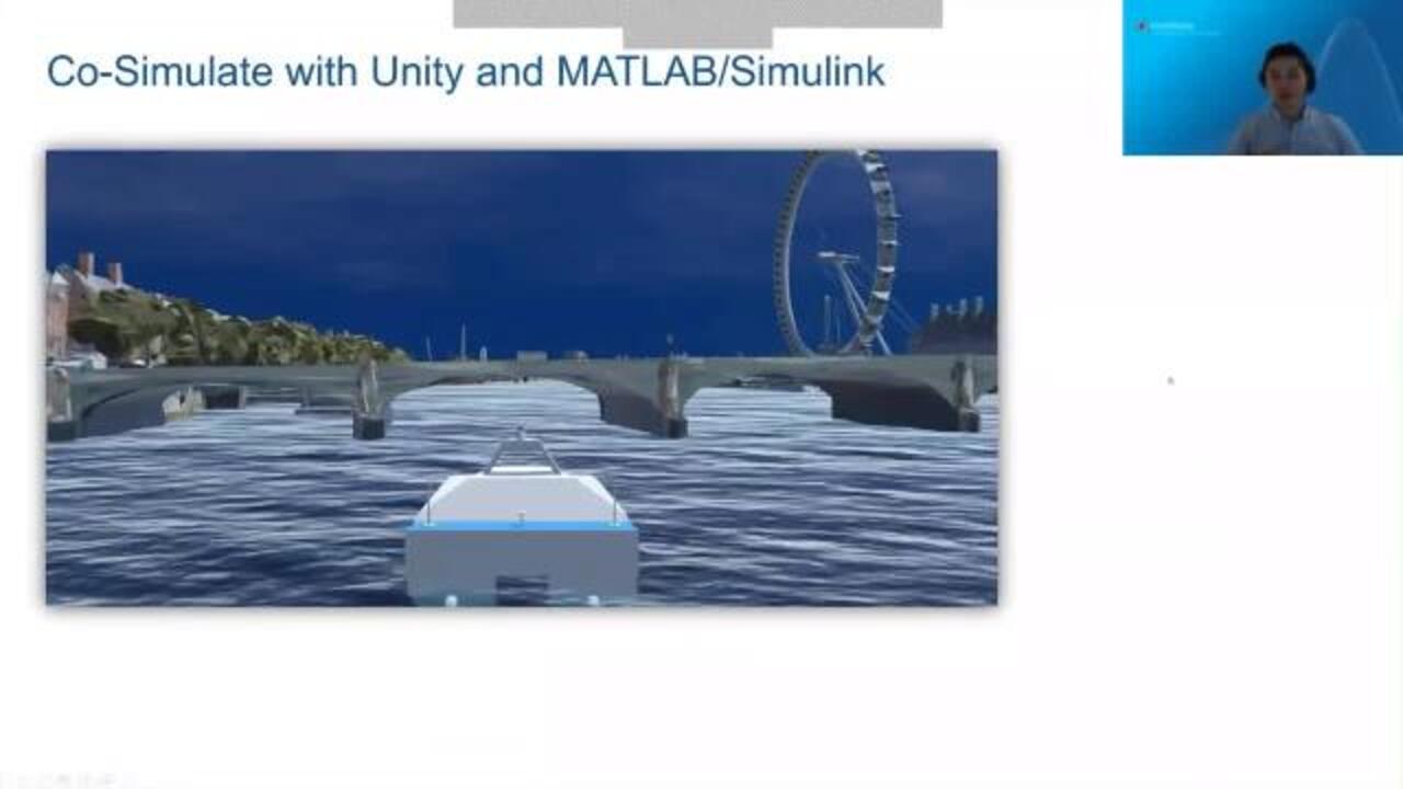
All right. The good thing though, is that we can somehow utilize these scenarios between different simulation environment. OK. Now, here I'm going to take Unity as an example to illustrate more details for you.
Here shows the co-simulation results with between Unity and MATLAB/Simulink. How we can connect Unity and MATLAB/Simulink is that it's either through DDS, or through ROS or ROS 2. From the ROS 2 box, we provide these Simulink blocks, or the method functions that allows you to interact with unity through the ROS. So here it shows the result.
Know that the automation and the algorithm and the vessel models are in Simulink, in this case. In Unity, we have a couple of sensors such as the Laser Scan. Here we have the Laser Scan model in Unity.
And we also have the ROS subscriber in Simulink. And Simulink received the latest scan from Unity. Here shows the result. Somehow the video doesn't work anyway. But you can see, it received the laser scan, from Unity.
Here also shows another virtual sensor. I'm sorry that the video doesn't work, except this one. So here, as I introduced, there are four camera sensor models, from in our vessel.
Here, with the ROS subscriber from Simulink, so we can receive all these images from Unity. We can also publish the data from Simulink back to Unity. Here, with that set, so that we can close the loop.
All right. Regarding Unreal Engine, instead of using ROS or DSS, we have the direct support for connecting Unreal Engine and Simulink. So here give an overview about the sensors. We offer this Ideal sensor, Depth sensor, and Semantic camera sensor. We also offer the Fisheye, LiDAR, and Radar sensor from Unreal Engine, in Simulink.
A summary? We offer these capabilities, all these features for developing the digital team of an ASV, as well as the scenarios. All right. With respect to time, I have the last slide.
We are also going to have the upcoming ASV webinar on June the 30th. If you are interested in knowing more details, so welcome to register. Thank you very much.

Featured Product
UAV Toolbox
Up Next:

Related Videos:


Select a Web Site
Choose a web site to get translated content where available and see local events and offers. Based on your location, we recommend that you select: United States.
You can also select a web site from the following list
Americas
- América Latina (Español)
- Canada (English)
- United States (English)
Europe
- Belgium (English)
- Denmark (English)
- Deutschland (Deutsch)
- España (Español)
- Finland (English)
- France (Français)
- Ireland (English)
- Italia (Italiano)
- Luxembourg (English)
- Netherlands (English)
- Norway (English)
- Österreich (Deutsch)
- Portugal (English)
- Sweden (English)
- Switzerland
- United Kingdom (English)