Model-Based System Engineering – Design, analyze, and test system and software architectures
Overview
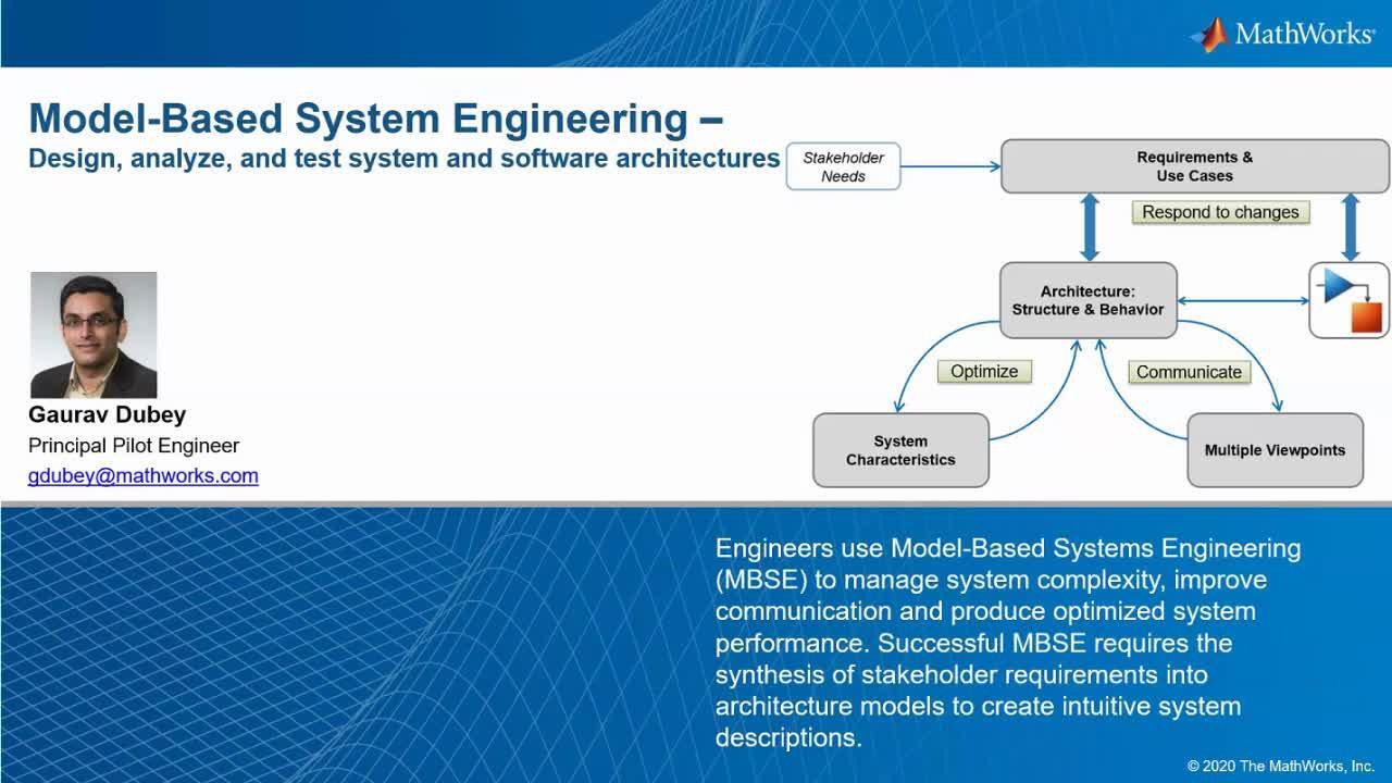
Today's engineering systems are getting more and more complex with frequently added complex requirements to shorten time of delivery to minimizing the field issues. Engineers use Model-Based Systems Engineering (MBSE) to manage system complexity, improve communication and produce optimized system performance. Successful MBSE requires the synthesis of stakeholder requirements into architecture models to create intuitive system descriptions.
MATLAB, Simulink, System Composer and Requirements Toolbox together provide a platform to create a single descriptive architecture models that seamlessly bridge into detailed implementation models. The connected environment ensures items across the architecture and design worlds stay in sync. Systems engineers can establish a digital thread to navigate between system requirements, architecture models, implementation models, and embedded software.
Highlights
Capture and manage system requirements enabling impact and coverage analysis
Optimize system architectures by capturing architecture metadata and directly connecting to MATLAB analytics for domain-specific trade studies
Create simplifying customized model views to isolate the components of interest for different engineering concerns
Validate requirements and verify system architectures using simulation-based tests
Translate and refine requirements into architectures with components ready for simulation and implementation using Model-Based Design in Simulink
About the Presenter
Gaurav Dubey is a Principal Application Engineer in MathWorks India and specializes in the fields of model-based systems engineering, model-based development workflows, automatic code generation, verification and validation, and certifications. He works closely with customers across industries to help them use MATLAB® and Simulink® products for System Engineering, model-based development, production code generation, and software verification and validation. Gaurav brings more than 16 years of experience in embedded system development for automotive and aerospace applications. Prior to joining MathWorks, Gaurav worked with Tata Motors Limited, where he gained hands-on experience in engine management system ECU development. He has also worked as a software analyst at Tata Consultancy Services on automotive projects involving model-based development. Gaurav holds a master’s degree in instrumentation engineering, and a master’s degree in electronics and communications.
Recorded: 5 Aug 2021
Good afternoon, everyone and welcome to MathWorks' webinar on model-based system engineering. We can do the design and analyze and test the system as well as the software architecture.
I'm Gaurav Dubey. I'm working as a principal pilot engineer in MathWorks based in Bangalore office. Have been working with the users for a long time on model-based system engineering topic.
Before we start, just a quick logistical information here. If you have any question during the webinar, please post it in the Q&A window. We have other model-based system engineering experts from MathWorks as our panelists. And they will help me in answering those questions.
If your questions are confidential, please direct them to the host. And very important part to keep an eye on the poll question that will pop up on the right of your window. These questions are to understand your uses of model-based system engineering and challenges that you are facing so that we can help you in overcoming those challenges.
Now what we are going to see in today's session, just a glimpse of that, is we will see that how we can capture the system architecture intuitively in the digital form, how we can create a digital thread across the different artifacts that we use throughout our development cycle to provide the traceability between a requirement architecture and the design, how we can connect our architecture environment or the system architecture with the design environment to do the system-level simulation. And while doing it, we will be utilizing the features of model-based design, which includes the multi-domain simulation to do the level compute system level simulation.
Now before we start, let's clear a few basics, right. A lot of you might be already aware of it, but people who are new to model-based system engineering-- first thing that comes in our mind is that what is system. So theoretical definition, if we look into the system, system is a group of interacting and interrelated entities. These entities has the defined boundaries, the structure and the purpose and expressed in its functioning.
So this is something we can represent as a system which is having a defined boundary. And it interacts with its surroundings. If we look into the more practical definition of that, we can consider a car as a system. It is having multiple components inside that, like engine, transmission, wheels, different ECUs, communication channels, et cetera, all them working together, interrelated with each other, creating one system we call car.
Now when we say the system, the first thing that comes in our mind is the system complexity, right. I took an example of a car, car itself is a very complex system.
We take a smaller example and see, understand, what is the system complexity that the system engineering can help us in coping with us An example is a car window. When the car was first introduced, there was no window at all.
A simple system, there was no component involved inside that. People start complaining about it, like all the debris and the dust falling on their face. Then the engineers came up with a fixed windscreen, which was a solution for the road debris, but not to the rain and the other wind that can come from the windows side.
Then the engineers came up with a solution of having a glass window. These windows usually were the fixed windows, or can be open in one or two steps. There was a component involved now in the system but was not that complex.
But then the stakeholders need-- which is stakeholders are nothing but the customers-- there need keeps increasing. And they said that we want to control how much the window will be open or closed. And then the mechanical engineer came in picture, implemented a few components inside that, like gears, crank, et cetera, and created a manually opening window.
Then the stakeholder requirement improved or increased. And they said, I want to automatically control that, or I want to control it with a button. And there comes the electrical engineer with his motor, unit of wiring harness, buttons, et cetera, so that we can get an electric window.
But again, the requirement keeps on increasing. And we know, by looking at the power window, we see just an electrical component. But in the background, it might be as complex as this, even more complex than that. This is a simple representation of an electrical window, which is having mechanical component, electrical component, electronics component, as well as a huge part of the software controlling the window.
So one single window, if I want to represent now, I need to create the whole architecture to show what all components existence in that particular system. And how they are interacting with each other, how they are impacting the behavior of the other components.
So the bottom line is that the system complexity keeps on increasing and system engineering help us in keeping up with that. And this is what the definition of the system engineering is. This is something that I took from the INCOSE website, that the system engineering is an interdisciplinary field. Means, it is having a multiple domain, people working together, and it focuses on how to design and manage complex systems over their lifecycle.
Now why do we go for the system engineering? Is the system engineering is about coping with the complexity? It helps avoid omissions and invalid assumptions.
So even before going for the design, system engineering can help us in understanding what all requirements are feasible. We can do a lot of the creative studies and understand what all requirements are conflicting with each other, and then take the right steps for that.
And this is what is visible. System engineering is not new. It's a very old concept. And you can see, even Einstein in his time mentioned that if he has a problem he would have spent 55 minutes in understanding the problem, thinking about the problem, and just five minute in thinking about the solution.
So this statement emphasized on the time we need to spend in refining the problem statements before even jumping to designing the solution. And system engineering help us in doing that.
Now again I'm going back to the INCOSE where there is a System Engineering 101 from the INCOSE. It talks about what is the correct way of implementing, or what is the right way of implementing the system engineering. There are the seven steps for the success-- understand the problem, investigate alternative solutions-- that means the creative studies-- define and agree upon the system architecture, because the multiple stakeholders involved, the need to first look how the system will look like, and then agree on that,
Agree and manage the requirements. First thing that you have to do before we move to any development is to have refined requirements.
Agree and manage the interfaces. Because there are multiple domain experts and designers involved, we need to agree to the interfaces and work accordingly.
Prepare the test and support system, and track progress against the plan. Now out of these seven, most of these activities we are going to see how we can address to model-based system engineering.
Now before moving to the practical example of implementing the model-based system engineering, let's see what is the system engineering workflow, the standard workflow that we can look into. As I mentioned, that everything starts with the stakeholder needs. You get a very rough level of requirements.
From there, you refine your requirements and use cases, put it in a more formal way so that it can be understood by the engineering team. From there, you create the system architecture. When I say system architecture, it can be any type of representation of it.
Most commonly used are the internal block diagram where you use the blocks to represent the components and the arrows to show how these components are interacting with each other or exchanging the data. Now on those components and the architecture, we specify its properties.
When I say properties, like if I have a component, maybe an engine. So what is the size of engine? What is the power, weight, cost, supplier?
These type of properties we define on those components and use these properties to optimize our architecture based on the stakeholder need-- cost versus performance or time to market or the overall behavior, et cetera. It's something that we can optimize. This is a highly iterative process, as we can understand.
Once you refine the architecture, you share this architecture across the stakeholders or across the engineering team and the domain experts. And for that, you need to create the views.
There is a different way the team might expect the architecture to look for. For example, mechanical team wants to see just the mechanical components of the car, while the software team wants to just look into the software ECU architectures of the car. So based on that, you need to create the different views and share it across the team, reduce the complexity. And this is a highly collaborative process, as there's multiple teams involved.
Once we pass these components to the design teams or the domain experts, they start creating the behavior of those components. At the architectural level, components are nothing but empty boxes, which are representing a component. But at a design phase, you start implementing the behavior of those components, which need to be linked with the architecture so that you can do the complete system level simulation.
And when we are doing that, our requirements have moved now from the system level requirement to the design level requirement. So we have the broader requirements now covering both architecture and the design. And these-- requirement, architecture, and the design-- should be connected with each other so that we can respond to the changes.
If something is changed in the requirement, we should be quickly able to understand what will be the impact on the architecture and on the design and take the appropriate action for that. And at the end, we are going to deliver a lot of the artifacts out of it, which include specification, interface, control documents, support code, and multiple more. So this is the generic workflow of system engineering, what we can implement in our basic day-to-day generic problem statement and can adopt it.
Now before we move forward, I quickly request you to have a look into the poll. It might be visible into your screen. And please do answer that.
The poll is about what are the challenges that you see or you are facing or you foresee that you might face in future when you adopt a model-based system engineering. If you are using a model-based system engineering, it's just that your architecture is not executable. It is just a static pictorial representation.
Or, your architecture is not synchronized with the design. Your architecture and design are in separate pools working in silos. Or, for a lot of the people, the architecture tool might be hard to use, leading to the steep learning curve. Or, your architecture is not analyzable. It is just, as I said, the pictorial representation.
So if you can answer the question, you can select the multiple options, whatever you feel is appropriate, and then please do answer that. So while your answering, I will move forward and see what the other people talked about that-- the same problem, same survey we did with the different people.
First what we asked them is that, are you happy with your existing system architecture tool. And only 8% of them, they said is that, yes, they are happy. The rest all are not happy with the tool. I mean, this is a common thing is that you are not always happy because the tools do not provide everything that what you're looking for. But 8% are only happy with their existing tools.
The question that I asked you just now, we got the response which is quite similar to the response that you provided us, that the problem that you face in your current tool is that those are not executable. And those tools are not synchronized with the design. So they work in silos. Those tools are used just to represent the pictorial architecture of your system, but you cannot do much beyond that.
There are few features available in the market which can help you in connecting your architecture tool with the design environments. But usually, those are not very smooth flows and results in the problem statement that has been shared by one of the customer, that "we have tried to build the architecture model in SysML and connect it to the design in Simulink." It just doesn't work. So even though on document, this is the workflow that we can adopt, but usually that doesn't work.
So what is the problem that we are going to solve when we say that you can do that in MATLAB and Simulink environment? When you develop your architecture, you develop in the tools like Excel, Visio, or any other SysML tool, or even on the PowerPoint, Word document, or maybe a paper napkin design.
But when you move to the design phase of your development cycle where you actually use the products like Simulink to design your behavior, there's a disconnect. You cannot connect or architecture smoothly with their design. And that is why we are going to build a bridge between the architecture and the design phase of your development.
So initial phases of the development includes the architecture design, the different type of representation of your architecture, your requirement, management, et cetera. While the later phase, we start doing the implementation in the model-based design.
The System Composer is a product that we launched in 19a. It helps you in bridging the gap between the model-based system engineering and model-based design.
But what goes into that bridge? I spoke about that bridge that we are going to do that bridge. But what goes in that bridge? What all activities we have to perform to say that, OK, we have a defined bridge for that?
As I spoke about, we start with the concept level, go all the way to the design. First thing what we want is that the tool should be intuitive to capture. It should be intuitive to capture the architecture in the tool and all its components. It should enable the implementation.
At the same time, the tool should allow you to create a digital thread between the architecture requirement and the design. Along with that, tool should allow or facilitate you to do the analysis at the architecture level so that you can do the different types of trade studies. What type of engine architecture will be better for my car, providing the cost versus performance criteria given by the customer? So that type of the analysis you can do. And you should be able to tackle the complexity inside your system, because your systems are now the system of system, which includes software, mechanical, electrical, electronics, and software, hydraulics systems all together, how we can cope with that complexity.
So the System Composer as I spoke about which we launched in release 2019a, it allow you to intuitively capture your architecture. It connects seamlessly with MATLAB so that you can do the architecture-level analysis. You can create the views out of that architecture so that it can help you in sharing your thoughts with the different domain teams. And it can connect seamlessly with the Simulink. So it allow you to do the architecture-level simulation, not just the design simulation also. And it connects with the Simulink requirements, which allow you to create a digital thread across the different artifacts during the development.
A good example here is Mercedes-Benz Research and Development India. They use the System Composer for defining their system architecture. There are few statements mentioned by the user there. There is a link given in the slide which will be shared with you where there's a video where they are talking about how they used System Composer for defining the architecture.
So what their target was, this process the developer has the access to the entire architecture while implementing a software and can relate to how the requirements are affecting the entire system-- digital thread. If you have a digital thread established, you change a requirement, you know how it's going to impact the overall architecture. At the same time, component engineer will know how its components is going to impact the overall system.
Now let's take an example and see how we can implement the model-based system engineering in your day-to-day workflow. As I mentioned, there are the different stages of your development cycle. It starts with stakeholder needs, goes to requirement, then you create an architecture, then you define the system characteristics and do the creative study. You create views to share with the domain experts. And then you implement the algorithm of the component in Simulink.
What we are going to do today is that we are going to take a simple example of a quadcopter. We are going to design a quadcopter, or the architecture of a quadcopter, which is expected to follow a green ball. Wherever the green ball in a free environment's going to move, the quadcopter will follow that. And we can understand, the quadcopter will have video capturing and the controls mechanism inside that.
So as I mentioned, everything is tied to the stakeholder need. One person came to me and said, the system shall be capable to fly for at least four minutes. There is an endurance requirement. Another stakeholder came and said that the system should be able to fit in a laptop bag. So that's a volumetric requirement.
So like this, we will be having a multiple type of requirement, like target should be green in color. It should be able to move in the three dimensional, and so on.
From there, we start defining the more formal requirements. Now it is something that we might be all familiar with is this is how a generic requirement document looks like.
From there, we defined the architecture for the system. In my system at a very high level, I understand that there is going to be a quadcopter. I represent that as a block.
And as a quadcopter is very small, pilot is not going to sit on that. To control that, I'm going to have the ground control station. There is another block for that. And there is going to be a target which is nothing but a green ball.
Now then I define how these components are going to interact with each other, whether the ground station will send some signal to quadcopter and receive some signal from the quadcopter. All these things I start defining in the architecture behavior. Then I start connecting these architecture components with the requirements because I need to represent which component is satisfying which requirement from the stakeholder.
Now when I'm defining an architecture, I have multiple options available in the market. There are a number of quadcopters available in the market that I can use to design my system. So which quadcopter is fitting into my stakeholder need? I start defining those properties of those quadcopter which I can get from the vendor on those component and start doing the analysis of those architectures to understand which is fitting into my need.
And as I mentioned, usually the architecture tends to become very complex, like a spaghetti model that you can see on the right-hand side of the screen. But for example, I'm a software engineer. I want to see the architecture. I don't want to see all these things which is having a mechanical component, hydraulic components, electrical components, et cetera.
I want to create a more filtered view of the components which are relevant for me so that I can read it and understand it. I can create a view which is relevant to the software engineer, or a view which is relevant to the mechanical engineer for the physical view so that they can focus only on their part, or maybe the different components which are falling into the different views. For example, on board processor, which is a physical component but also is a part of a software view because it is having a software running on that.
But once all this thing is done, we share these views with the different teams, those teams start developing the algorithms for those components. So we connect the behavior of those components with the architecture.
Now having said that, the different activities that I mentioned starting from requirement, architecture, trade studies, integration, et cetera, a quick poll here is that which all activity of model-based system engineering you are working on or you are planning to work on. Whether you focus on the system requirement or the requirement engineering, or you also work on the architecture design, architecture-level analysis trade studies, or you also go all the way till the complete system level simulation and analysts.
But please do answer that. Whatever is relevant for you, please select that and answer that. So we are going to see that how all these activities can be done in Simulink environment with an integrated view and integrated toolchain.
Now I will move forward. Let's see how the tool can work. Let's see it in the action. So as I mentioned that everything starts from the requirements.
Now you can define your requirement in any tool. It might be Word, it might be DOORS, it might be Excel sheet where you want to use it. Simulink also provide the same environment, what we call the Simulink requirements.
In Simulink requirements, either you can import your requirement in your design environment, which is Simulink and System Composer, or you can alter your own requirements or you can edit all the important requirements. Everything can be done in the single environment.
So if you can see here, this is an interface of Simulink requirements. If I go, I have a hierarchical requirement where I'm showing here stakeholder need of the quadcopter to fly for four minutes, as well as I captured that it should fit into the laptop bag.
From there, I have the target characteristics, like the target should be able to fly in three dimensions. It should be green in color. So whatever the requirement to capture in any tool or in any format you can capture it inside the Simulink requirements or import it inside the Simulink requirements.
Why we are doing it? So that you can have requirement and design and architecture in the single environment. What is the benefit of it? I'm going to show in the next few slides. So once we have the requirements ready, whether it is in your tool, a third-party tool, or in the Simulink environment, the next phase of the activity is defining the actual architecture.
Now at very high level, as I mentioned that I have three components-- ground station, quadcopter, and a green ball. And ground station and quadcopter interacting with each other. How are we going to represent that part, represent that architecture?
So the environment that you see is called System Composer. What do you have to do is just thread and create a box which represent your ground control station and vehicle, as well as your green ball. Then we will specify that there will be one signal moving from ground station to vehicle. Let's called that commands. And then the vehicle will be sending the telemetric data back to the ground station. It is as simple as that.
Now I can go inside the vehicle and start designing the components inside the vehicle. It is a hierarchical diagram. I can go deep inside each and every component to start designing the architecture for that. At very high level, this is how my overall system will look like. It is as simple as creating box and connecting the signals.
When we are doing that, these boxes are nothing but what we call components. These are called ports, which are the entry and exit point from those components. And these are the connectors, which represent there is a message or the signal flowing from one component to the other component.
Now we start creating this architecture. Assume that you define the architecture in detail. We can go inside the vehicle and start defining that there is a motor, there's a propeller, there's a controller, there's a payload which is having a camera, and so on. All that components I can start defining in the vehicle.
But after that, the next phase is to represent which component I added for which requirements. Or which component is satisfying which requirement? And for that, what we do is what we call requirement allocation.
So if you remember, I imported the requirement inside the Simulink environment. And that is exactly you can see just below your editing tool. What you have to do is just drag a requirement and drop it on any of the components.
This activity creates a bidirectional traceability between the components inside your design and the requirements. Now these two are connected. If you click on a component, requirement will be highlighted. If you click on a requirement, a component will be highlighted. And that's how you can create an allocation between the requirement and the architecture.
Now in this case, if I change a requirement, it will immediately highlight a component inside an architecture and will tell me this is the component which will be impacted because of the requirement change. So if you see an overall view here, through this we can press the system requirement with the architecture using the Simulink requirement tool.
At the bottom, you can see the requirements right there just below your editing canvas. And the moment you connect the requirement with the architecture component, you can see that requirement is now visible on the editing canvas with the arrow linking the requirement with the component. Now it is easy for me to review, to audit this whole architecture, to understand which component is implemented for which department, or which requirement is implemented by which component-- multi-ways.
Now once that is done, the next phase of any architecture design is defining the interfaces. So what do I mean by defining the interfaces? So in the beginning, I mention that the ground station will send command to vehicle, and vehicle will send the telemetric data back to the ground station, which, to represent the overall system and how the components are interacting with each other, is sufficient enough.
But then I want to move this vehicle, for example, to a design engineer and tell the design engineer, vehicle is supposed to get the commands. How the design engineer will understand, what do you mean by command. What all goes in this word command.
And that is where we have to specify the interface information on each and every port so that it can go to the design engineer, and even for the domain expert can read it and understand what do I mean by command.
And how can we do that? It is as simple as that-- creating a bus object in Simulink. I created one variable or one object create name command. I selected a port and assigned that command interface to that. So the moment I click on the port, interface is highlighted, and vice versa.
Now in that command, I can create the members or the components in that. For example, my ground command will have take-off, landing, and, let's say, emergency stop commands going to the vehicle.
The moment I do that, now for each and every of these takeoff, land, and emergency stop, on the stop you can see I can specify what is its dimension, what is its unit. What is the minimum/maximum values? What is the description of this variable or the signal?
So what happens is that when I pass this vehicle component to the design engineer, that engineer will understand that I am going to get three signals from the ground station. These are the data types and the specifications of the signals. And now I can start designing the behavior accordingly.
So interface information is very important, very critical part of the architecture designing. Because when you get these components from the different designers and try to connect it together as an integration engineer, most of the cases we find an issue because the interfaces are not maintained properly or are not synchronized with each other.
And these are the interface control document can help you in doing it. Now inside the System Composer, we can define these components and these interfaces. And these interfaces as it is, will be used inside the Simulink, because they use the same bus objects. So there will not be any mismatch between the design phase and the architecture phase of .
So as I mentioned, so you can create the interfaces. Now once you create the interfaces, our architecture design is ready, the interfaces are ready. Now we go to a stage one step forward, and then start defining more properties on the architecture. We can start capturing the system characteristics and properties. This is something what you might have heard about is the profile and stereotypes.
Now on my architecture, I have different components. For example, I have a quadcopter vehicle. Now this vehicle has some cost. This vehicle has some battery capacity. This vehicle has some weight, thrust generation, et cetera.
I should be able to capture those properties on the vehicle component or on the battery or on the motor which I used inside the architecture. Let's see how we can do that.
So if you see here, in my case, I created three different architectures. Why I created three different architectures? Because I have three different quadcopters available. One is an FPV camera with radio communication. One is RPI, Raspberry Pi with radio communication. Or I can use Raspberry Pi with Wi-Fi communication.
Now I have three different architecture. Any one of this is something that I want to take forward for the design phase. I don't want to do the designing for all three. Because at the end of the day, I'm going to use one of it.
So I need to do the analysis that which quadcopter architecture or which system architecture is going to fit into my stakeholder needs. For doing that, I need to define a few properties on the architecture. So when I said properties on the architecture, what do I mean by that?
We can define a stereotype. For example, I select a quadcopter. On the right-hand side, you can see there are multiple properties captured for that-- what is payload capacity, what is battery capacity, cost, endurance, airframe mass, total mass, power draw, et cetera.
Now these properties are static properties. I can get it from any data sheet. I specify it on the quadcopter so that I can use it for further calculation. I go inside the quadcopter architecture and I go to the payload. payload for me is nothing but the camera.
So if I go further inside, I can see camera. I have camera properties. What is the mass of the camera? What is the power draw of the camera?
As you can imagine, the mass and the power draw is going to define how long my quadcopter is going to fly. I go to all three different architectures and start defining these properties for the components that I'm using. Whether it is in Raspberry Pi based quadcopter, or it is some other controller-based quadcopter, or different quadcopter vehicle platform itself.
I start defining these properties. And why do I define those property? So that I can do the analysis on that particular architecture.
So what you are seeing right now here at the bottom is what we call analysis viewer. This is an inbuilt feature of the System Composer, which help us in connecting our architecture with MATLAB engine in the background. Use the MATLAB analysis capability to do the trade study or the analysis at my architecture level.
So if you remember, my requirement from the stakeholder was that my quadcopter should be able to fly for at least four minutes-- endurance, four minutes. What I'm going to do is that I'm going to calculate the endurance of all three architectures and figure out which is fitting into my budget and which is fitting into my requirements.
So the view that you are seeing here is called the analysis view of the quadcopter. In this, all the three components, all the three architectures are defined. If you can see on the left-hand side-- FPV camera with radio communication, RPI with radio communication, and Raspberry Pi with Wi-Fi communication.
This view captured all the different properties inside the architecture, called the MATLAB script in the background, and do the analysis on my architecture. So when I did that, when I ran my MATLAB analysis on my three different architectures, it calculated the different properties out of it.
And what I figured out is that only the first architecture is having an endurance of 4.13. Rest two are around 3.8 and 3.9. When I said 4.13, it means 4.13 minutes.
The moment I did that, I can highlight only the one quadcopter, one system architecture is fitting into my stakeholder need of four minute flying. So I can scrap other two architectures and can take the first architecture, which is FPV camera with radio communication for the further detailed design, high fidelity design of those components and pass it to the design teams. So at architecture level, I can quickly do a trade study and analysis and figure out which one I want to go forward with.
Now once we do that, I need to pass this architecture to the design team. So when I say I need to pass the architecture to the design team, the whole architecture will not go to one team. This architecture has few physical components, will go to the mechanical and plant modeling team. Software components, which will go to the software teams and electrical components, and so on.
So I need to create the views. For example, I want to create an architecture view to the physical modeling team. So what I can do is that I can just create a filter, then give me a view of all the physical devices. The moment I do that, I can create a view. And as you can see this complex architecture will be filtered out but the components, which are having only physical properties.
All the components which will go to the either mechanical engineer or the physical modeling engineer. And I filtered out all the relevant components outside that.
So not only that, we can create different other views. For example, hierarchical diagram we can create out of the same architecture. On the right-hand side, you can see the hierarchical diagram, which represent my same architecture that I created more into the functional decomposition view.
Like in my camera module, I will have a camera and a power switch. What was the ports of that camera and power switch? What are the properties of those components, et cetera, will be visible in the hierarchical view? So a lot of the people prefer to look into the architecture as a decomposition view.
Not only that, I can use the same architecture to define more behaviors of the architecture or behavior of the system-- for example, a sequence diagram. So on the right-hand side, what you can see is the sequence diagram of the block diagram that we created on the left-hand side. It represents how the signal will be passed from one component to the other component. Or in this case, we call that lifeline. And how the signal will be written back, what processing will happen, and so on.
If I create a different lifeline in the sequence diagram, automatically components will be created. If I create communication between the lifelines, it will be automatically created inside my architecture. So both are synchronized with each other, whether it is a sequence diagram or it is a block diagram that I created.
Now what we have done is that we created the filter view. We created the different views and passed it to the design teams. Now design teams are going to specify the behavior of those components. And they use the Simulink to do that. What we need now is to connect our architecture component with the Simulink behavior.
So we can connect the System Composer with Simulink in model-based design by simply calling the Simulink models behind those components, whether it is a physical component or it is a control or the calculation algorithm mathematical models, and just simulate the whole architecture. How can we do that? We can have a quick view here.
So this is the internal architecture of my onboard processor in which I have a component for a communication interface. What I can do is that in that component I just specify there is the Simulink behavior of that component defined. The moment I define the Simulink behavior, you can see the ports are automatically created because it took it from the Simulink models already.
What I have to do is that I have to connect this component with the rest of the architecture as simple as just dragging the signal and dropping it on the component. If I go to the Simulink design and, for example, if I make any change in the design. That's supposed to create and port here,
Now for this port, if you remember, I specified the interface information at the architectural level. I can use the same interface information at the Simulink design level. I don't have to recreate the interface so that I there is no mismatch in the interface when I connect the different components.
The moment I do that, a new port is created at the architectural level for that component. What I have to do is simply connect it with the rest of the components. And now my Simulink, the architecture, is ready with the Simulink behavior, and I can simulate and analyze the whole architecture at the system level. I don't have to do the component-level testing. I can do the complete system-level simulation.
And the moment that is done, what is the next stage? I start doing the testing of my system. And for that, I'm using Simulink Test, which is our test environment. I can link my test scenario with the requirements. I can provide the triggers. Triggers are nothing but the simulation test scenarios to the architecture and just click Run.
And the moment I do that, now you see, whatever you see the graphics here, is actually the complete system simulation which includes the plant, the quadcopter. It includes the controller. It includes the communication, everything inside that.
Now when I do the complete system-level simulation, I can go and see the behavior of my complete system. So what I'm doing here is that I'm just opening the x-axis movement of my ball. So if you see here, I have the x-axis movement of my ball, which is a sort of a sinusoidal waveform at the end.
And just below that, I have the actual quadcopter movement, which sort of following the ball as we expected. I can look into the results and analyze that what exactly my behavior is, that it is fitting into my requirement or not. The bottom line here is that I'm simulating the complete system and not just one component in that.
So what we have seen so far, this was our initial flow or the workflow for the model-based system engineering. What we have seen is that we can use Simulink requirements to capture our requirements, can use the System Composer to create and define your architecture, use the properties to link it with the MATLAB environment and do the trade study and analysis, create views to share it with the different stakeholders, and, at the end, connect our architecture with Simulink behavior so that we can do the complete system-level simulation.
And while doing it, everything is connected with a single digital thread so that any change in our system will directly be captured in the different artifacts and can be seen what will be the impact on the different artifacts for any change in the requirements, architecture, or in the design. Now having said that, you understood-- I hope you got the basic behavior or basic workflow of system engineering and how we can implement that in System Composer.
There's another poll where I would like your input is, how do you do or how are you planning to do your architecture design, whether you are majorly using a PowerPoint, Word, Excel, or do you do it on the whiteboard, or you use a bit more sophisticated tools like Rhapsody, Enterprise Architect, MagicDraw, or any other SysML tools that you are using. For this, please do enter your response in the chat window.
I hope you entered your response. If not, please do so. So the workflow that I spoke about is not something which is new. It's being used by the different customers-- Mercedes-Benz India, R&D India, I already spoke about. There is another paper which is published by MathWorks and the Gulfstream that how this workflow can be adopted for model-based system engineering.
As you can see, the title of that-- "System Architecture Modeling for Electronic System using MathWorks System Composer and Simulink." So this paper speaks about that how the Gulfstream developed the electronic system architecture using the System Composer and Simulink. Following the same workflow that I spoke about.
There are more links available. When you will get these slides, these links will be available for you. You can go through that. There are a lot of the material available on the MathWorks website where you can learn about the different stages, different steps, and the different features of the tool that you can use for your model-based system engineering workflows.
Featured Product
System Composer


Select a Web Site
Choose a web site to get translated content where available and see local events and offers. Based on your location, we recommend that you select: United States.
You can also select a web site from the following list
Americas
- América Latina (Español)
- Canada (English)
- United States (English)
Europe
- Belgium (English)
- Denmark (English)
- Deutschland (Deutsch)
- España (Español)
- Finland (English)
- France (Français)
- Ireland (English)
- Italia (Italiano)
- Luxembourg (English)
- Netherlands (English)
- Norway (English)
- Österreich (Deutsch)
- Portugal (English)
- Sweden (English)
- Switzerland
- United Kingdom (English)