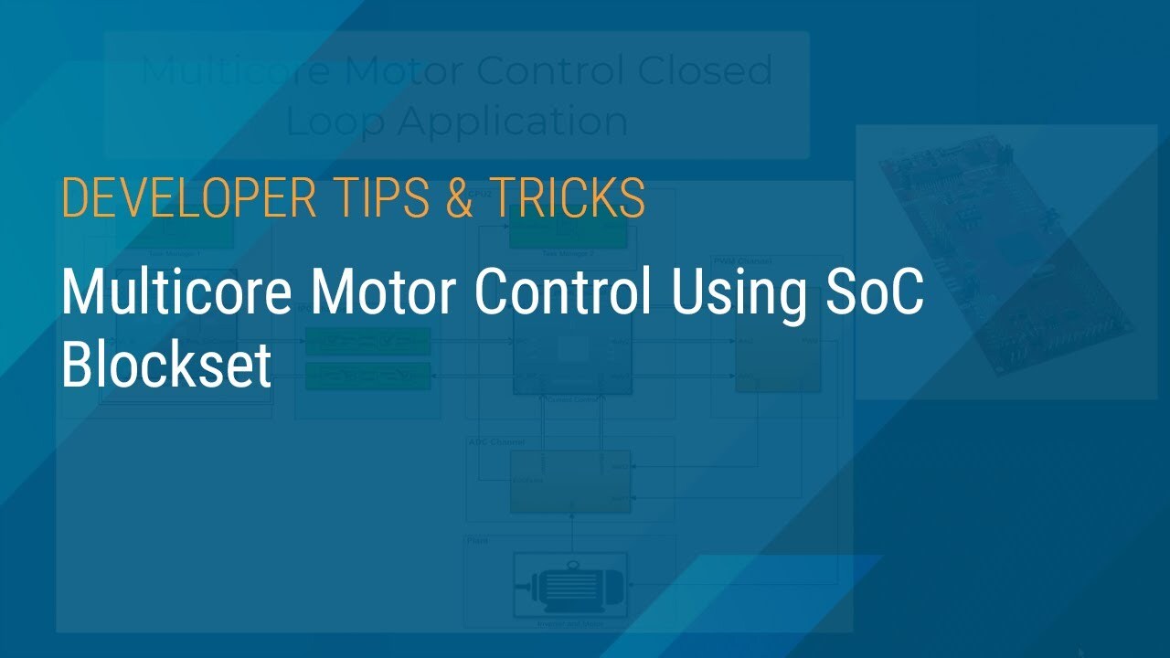
Multicore Motor Control Using SoC Blockset
Learn how to use Model-Based Design to develop controllers for multicore microcontrollers. Follow along with a demonstration of a field-oriented controller (FOC) for a permanent magnet synchronous motor (PMSM). In this example, blocks from SoC Blockset™ are used in Simulink® to model the hardware architecture of a TI C2000 multicore MCU.
The process begins by simulating the controller in Simulink with the entire FOC controller assigned to one core of the TI C2000 F28379D MCU. However, simulation in Simulink shows that the current controller task will overrun, leading the controller to fail.
The demonstration shows how to use SoC Blockset to partition the controller with speed control and position estimation assigned to one core and the current controller to a second core of the MCU. This time, the simulation indicates that the controller will perform as expected with correct rise time and settling time.
Published: 19 Oct 2021
Hello, everyone. My name is Pradeep. I'm a Development Manager at MathWorks.
Are you facing challenges in partitioning control algorithm for multicore MCUs for motor control application to achieve higher performance? If yes, then I'm going to show you how you can use SoC Blockset to partition real-time motor control application to run on multiple cores, and analyze the higher PWM frequency effect on control performance in simulation phase, and then verify the tuned controller on the hardware.
SoC Blockset enables model based design for multicore microcontrollers based application development. It provides multicore architecture modeling with IPC communication, out of the box support for programming multicore MCUs like TI C2000 F28379D, guided deployment workflow using SOC builder app.
I am using a C2000 Delfino MCU F28379D LaunchPad development kit to verify the behavior on the hardware. Here, we see a Simulink model that represents the motor control closed loop system. This model simulates dual core motor controller for a permanent magnet synchronous motor inverter system.
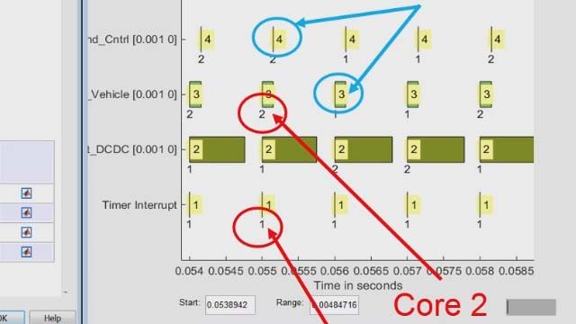
Task Manager block, highlighted in green, simulates the execution of software tasks as they would be expected to behave on an MCU. The Task Manager executes individual tasks based on the parameters, such as period, duration, trigger, priority, or processor core, and the combination of that task with the state of other tasks and their priorities in the running mode.
Tasks can be timer driven or event driven. Inside a single reference model block, the timer driven tasks are represented as rates, and event driven tasks are represented as function call subsystems. Multicore model contains at least two task manager blocks, each connected to a more referenced block representing the process to be run on a separate core. The controller subsystems highlighted in green, represents the partition algorithms running on different cores.
The current control is running on core two, and the speed control and position estimation is running on core one, respectively. The blocks highlighted in green color represents the interprocess of communication data channel, using which, processors can communicate to each other asynchronously. interprocess communication consists of the data write, data channel, and data read blocks.
The interprocess data write block asynchronously sends message to another processor in an SoC using an interprocess data channel. The interprocess data channel block provides a channel for asynchronous data transfer between two processes. The interprocess data read block asynchronously receives messages from another processor in an SoC using an interprocess data channel.
Now let's see the model configuration for multicore architecture. Click on the System on Chip tab, and then click Hardware Settings to open the Configuration Parameters window. In the Hardware Implementation tab, the processing unit parameter is configured to none, indicating that it is the top level system model.
Now let's open one of the referenced model within the system model to see how it is configured to run on a specific core. In the Hardware Implementation tab of reference to model, the Processing Unit parameter is configured to c28xCPU1, indicating that it is configured for core one.
Now let's talk about how you can leverage additional cores to achieve higher loop rate by partitioning the control algorithm to run on multiple CPUs. Let's begin by looking at a problematic case where motor control algorithm is running on single core. Generated PWM frequency is 40 kilohertz. The execution time of current loop task run by ADC interrupt is 26 microsecond. The execution time of speed loop is 5 microseconds. Run the simulation and view the results in SDI.
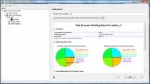
As you can see in the picture, the speed feedback from the motor is zero, where it is expected to follow the reference speed highlighted in green color. This is because the current loop task is running, leading to the drop off of speed loop tasks as shown in the below graph. With 40 kilohertz PWM frequency, the current loop is expected to finish its execution within 25 microseconds. You can also analyze this behavior on the hardware, using the task profiling capability of SoC blocks.
To address the issue with the single core model, let's partition motor control application across two cores of the TI C2000 F28379D. We partition the control algorithm by executing current control on core two, and speed control and position estimation on core one respectively. Data transfer between the cores are handled by interprocess data channel block, as I explained earlier. Using both cores to execute control algorithms allows us to achieve higher control of bandwidth. Now run the simulation and view the results in SDI.
In this figure, you can see that at 40 kilohertz PWM frequency the speed feedback from the motor is tracking the reference value as expected. Now let's proceed with programming the TI launchpad board to verify the behavior with the hardware test. Follow the instructions on the SoC builder tool to run the model in extreme mode and view the results in SDI. This figure shows the controller response from simulation and deployment at 25 microsecond current loop, with 40 kilohertz PWM frequency. Compare with 50 microsecond current loop at 20 kilohertz frequency. As expected, the rise time and speed improves with faster current loop by approximately 50%.
So to summarize, you can easily identify and fix the design problems in multicore based motor control application early in the development phase using capabilities in SoC Blockset like multicore architecture modeling with IPC communication, out of the box support for programming multicore MCUs like TI C2000 F28379D, guided deployment workflow using SoC builder app.
Thank you so much for watching. To try the example, please visit the link mentioned in the video description.
Featured Product
SoC Blockset


Select a Web Site
Choose a web site to get translated content where available and see local events and offers. Based on your location, we recommend that you select: United States.
You can also select a web site from the following list
Americas
- América Latina (Español)
- Canada (English)
- United States (English)
Europe
- Belgium (English)
- Denmark (English)
- Deutschland (Deutsch)
- España (Español)
- Finland (English)
- France (Français)
- Ireland (English)
- Italia (Italiano)
- Luxembourg (English)
- Netherlands (English)
- Norway (English)
- Österreich (Deutsch)
- Portugal (English)
- Sweden (English)
- Switzerland
- United Kingdom (English)