Optimize EV Battery Performance Using Simulation
In early vehicle design stages, engineers need to make decisions about battery pack sizing. This often involves trade-offs between competing objectives such as EV range and cost, making it difficult to select an optimal design. It requires significant time and modeling expertise to build the closed-loop system-level models needed to evaluate potential designs.
In this talk, we present an accessible workflow to address these pains. We demonstrate how to create a system-level electric vehicle model using the Virtual Vehicle Composer app from Powertrain Blockset™. The model will be used to iteratively evaluate the vehicle’s performance using optimization techniques. The results of this study can then be used in Simscape Battery™ to generate an appropriate battery pack design and evaluate the pack behavior in more detail. This battery model is then integrated back into the system level model for verification against the requirements.
This approach provides a rigorous numerical method to quantify trade-offs in the design problem. It also simplifies the process of model building, both at the system level and battery subsystem level. Domain experts who may not be tool experts can now take advantage of these powerful design workflows.
Published: 7 May 2023
[AUDIO LOGO]
So, welcome everybody. My name is Lorenzo Nicoletti. I'm an Application Engineer at The MathWorks And prior to joining MathWorks, I did my PhD in automotive engineering with a focus on electric vehicles. And today, I am joined also by my colleague, Danielle Chu, who is going to introduce herself later on in the presentation.
And today, we're going to talk about the topic optimize electric vehicle battery performance using simulation. So before we start, I would like to encourage you also to share your MATLAB EXPO experience by using the tag #MATLABEXPO. And if you want to contact me or Danielle, you'll find here below also the links to our LinkedIn profiles.
So what are the key takeaways of today's presentation? So today we want to show how you can create a full-vehicle model to assess the system performance of a Battery Electric Vehicle. So we're going to use the Powertrain Blockset. And we're going to create a Battery Electric Vehicle model that we will use to estimate range, battery performance, and costs.
Then we are going to show how you can use this model to perform an optimization-- in this case, to find the optimal battery size. And then we are going to show how you can further detail the battery by using a new product, which is Simscape Battery.
Before we start, however, let's see the problem statement for today's presentation. So why are we talking about this? So today, the automotive sector is focusing on reducing the CO2 emission. And for this scope, Battery Electric Vehicles are a promising solution because they localize the emission directly to the energy production source, and they can be charged, also, with renewable energy.
However, there are still engineering challenges. We can see this if we compare a lithium ion battery with a conventional diesel tank. So here are three big differences. As we can see, the lithium ion battery requires a much larger volume, has a much larger mass, and at the same time, is not capable of installing the same amount of energy than a conventional diesel tank.
On the other hand, it also has to be noted that the electric powertrain is more efficient than the diesel powertrain. But this is, however, not enough to compensate for the mass and volume disparity between the two systems.
So for this reason, usually the battery is one of the heaviest, the biggest component in the electric vehicle. And therefore, it inevitably impacts the parameters such as the vehicle mass and, of course, also other crucial system-level specifications, such as energy consumption, range, and deceleration.
Therefore, its integration in the vehicles still represent a major challenge for the automotive manufacturer. And today, our goal is to show how you can use the MathWorks products to create a Battery Electric Vehicle model to assess the vehicle performance, meaning energy consumption, range, acceleration; how you can use this model to optimize the battery pack size; and finally, how you can further detail the battery pack size with the Simscape Battery.
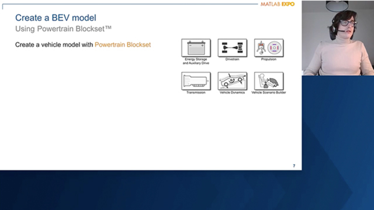
So let's now move to the first step, which is create a Battery Electric Vehicle model. So for this step, we are going to use the blocks from the Powertrain Blockset. With the Powertrain Blockset, you can create a full-vehicle model. You have different blocks for gasoline, diesel, hybrid, and electric systems, meaning that you're not just limited, also, to electric vehicles.
The Powertrain Blockset provides, also, a standard model architecture that can be reused throughout the entire development process. And it's also ideal for trade-off analysis, component sizing, and optimization, as we are going to show today.
If you don't want to create your model starting from zero, you can also use the Virtual Vehicle Composer, which is an interactive app that has several prebuilt vehicle templates. For example, it has a prebuilt Battery Electric Vehicle template. It has an easy component parameterization. And you can use the app to parameterize the vehicle as you like. And once you're happy with the parameterization, it automatically generates a full-vehicle model.
Also in this example, we will use the Virtual Vehicle Composer. And with the help of the Composer, we generated a full-vehicle model for our Battery Electric Vehicle. And this is how the model looks like. So we can see there is a block where we can set the drive cycle or the maneuver that we want to simulate. We can account for environmental parameters, such as air pressure and temperature.
The model also has a driver model, which is going to ensure that my vehicle follows the given cycle or maneuver. There are different controller-- for example, controllers for torque blending. And here we have all the plant models or the powertrain models and the chassis models.
So now that we have a model of our vehicle, we can parameterize it as we like. In this case, I've chosen the parameterization of a mid-size passenger car. Here we can see the main parameter that I've chosen. We can also see that I assumed a certain battery size, a certain gearbox ratio, and also some assumptions regarding the battery energy density and the battery costs.
So once my vehicle is parameterized, it's ready to be simulated. So first of all, you can perform, for example, a drive-cycle simulation, such as a WLTP drive cycle. And you can see here how the state of charge of the battery changes during the cycle. And we can use this result to estimate, then, the range of the vehicle. And since I assumed a certain battery size, you can also use the battery size assumption and the battery cost assumption to derive what the battery cost will be.
You are not just limited to drive cycle simulation. You can also use the model to simulate an acceleration, like a wide-open throttle test. And from these simulations, you can then estimate the acceleration time-- for example, for 0 to 100 kilometers per hour of your vehicle.
So now that we have our full-vehicle model, we can perform an optimization of this model. In this case, we're going to focus on optimizing the vehicle to find the ideal battery pack size. But what is the ideal battery pack size?
So first of all, we have to define objectives, constraint, and our design variable. So our objective is going to be we want to design the Battery Electric Vehicle so that it provides a reasonable range at an acceptable price. And we can express this objective as a cost function, which depends on the cost of the vehicle and the range. And we're going to minimize this cost function.
At the same time, we have some constraints. So our vehicle must be able to follow the drive cycle. It must still have a reasonable range, as I said, and also a reasonable acceleration. So we can express these constraints here as follows.
And finally, we have to choose the design variables. So these are the variables that can be changed during the optimization in order to find the optimal solution. So as design variable, we have chosen the battery cells in parallel and the battery cells in series so, basically, the battery dimensions, and also the gearbox ratio. And we can express the design valuable as follow.
Also, here, I didn't let the algorithm vary this design variable freely. As we can see, there are ranges. For example, the number of parallel cell must be comprised between 10 and 50, and it must be an integer number. So I cannot have 10.5 cell or 11.5 cells. I can only have 10 or 11. On the other hand, we can see that the gearbox ratio is a continuous variable that varies continuously between 7 and 10.
So now that we have our constraint and our objective, we can go back to the results of the first assessment that we did. And we can see that the first vehicle I simulated has an acceleration time which is acceptable. So it's below our target of 7 seconds.
However, if we look at the range, we see that our range is below the objective of 400 kilometers. So there, we need to optimize to improve the range. And at the same time, in the initial assessment, I could derive some costs. But this is no guarantee that these costs are optimal. So using an optimization algorithm could allow me to identify a cheaper vehicle with a higher range.
So now that we have set up everything, we still have to choose a suitable optimization algorithm. And for these, we have to take into account different requirements. So for example, we have to consider, how does the design variable space look like? Do we have continuous variable, such as our gearbox ratio, for example? Or do we have integer variable, such as the number of cells? In our case, we have both, which would be, then, a so-called mixed-integer case.
Another requirement we have to consider-- do we want to perform a local or a global search space? In our case, we decided to perform a global optimization by using the Global Optimization Toolbox. And then finally, once we have chosen which optimization toolbox to use, we also have different algorithms that we can choose from.
So in our case, we decided to use the surrogate optimization. Here are the main advantage of this optimizer. But the most important one is that this optimizer uses, normally, fewer function call than other global optimization solvers, so we opted for it in order to find as fast as possible, also, an optimal solution.
So now I'm going to show the results, and I'm going to compare them with the initial assessment. So we can see here our representation of the solution space. So we have the range and the battery cost. These are the two objectives that we want to optimize. And we also see the cost function. I want to minimize the cost function. So, ideally, I want to be in the dark blue area. This is, however, not physically possible.
We can see here that our initial assessment is positioned here, and it is below 400 kilometers. So it's not in the acceptable range. And then represented here-- all the points that were tested by the optimization algorithm. And you have to imagine each point here represents a different vehicle with a different range, different battery size, and so on.
And finally, the algorithm identified, here, the optimal solution, which is the solution that maximizes the range while minimizing the costs. And here we can see, also, the final results. So we can see that our new solution has a range above 400 kilometers. We know that the costs for this solution are also optimal. The acceleration time has not changed. And we can also see how the transmission ratio and the number of cells has changed in order to identify this optimal solution.
As a final note, this algorithm performed a total of 300 function call and converged within 2.5 hours. This was done on my laptop. I did not use Parallel Computing. If you want to further accelerate the optimization process, you can also use Parallel Computing.
So now that we have identified an optimal battery pack, I'm going to hand it over to Danielle who is going to show how you can further detail the battery using Simscape Battery.
Thank you, Lorenzo. Hello, my name is Danielle Chu. I have been a Product Manager at MathWorks for two years. Prior MathWorks, I worked at John Deere for several years on power electronics control and control system integration. Today, I will be covering the battery design section.
I'm not going to show the details of the design or the design outcome. Instead, I walk you through the design workflow and how things give battery supports the design along the workflow. The battery design study workflow has five steps.
Step one is to size battery pack within context of full-system operation, which Lorenzo just covered. Step two is to create a lumped battery pack model in Simscape Battery and demonstrate equivalence. Step three is to design battery system in Simscape Battery. Step 4 is to select appropriate modal fidelity for full-system evaluation. Finally, the last step is to evaluate battery design in full system.
The tool we use in the battery design is Simscape Battery. It provides design tools to design and simulate the battery and energy storage systems, including electrothermal cell behavior, battery pack design, and battery management system.
With Simscape Battery, you can evaluate battery pack architectures for electrical and thermal requirements; verify robustness of discharge, charge, and thermal management algorithms; and validate the algorithms using hardware-in-the-loop testing.
Simscape Battery models integrate directly with block diagrams in Simulink, state machine Machines, in Stateflow and macro functions. And you can simulate your entire system in a single environment.
Because we have users using Simulink battery model like the one in Powertrain Blockset on the left, which is a lumped representation of a battery, before going to the details of battery design in Simscape Battery, we would like to demonstrate the equivalence of Simscape battery model and lumped battery pack model in Simscape Battery.
On the right, we took the parameterization from the Simulink battery model and used it to populate the battery model in Simscape Battery. We ran a unit test to demonstrate the two battery models are equivalent using the same current and temperature profile of the Simulink Battery model and run through the created lumped battery pack model test harness.
The true voltage are within a very small tolerance, which builds confidence that we are operating on the same battery characteristics. The lumped battery model for the entire pack is just a single cylindrical cell model as shown on the left. With Simscape Battery, we can create a battery pack with higher resolution depending on your design or simulation needs.
For example, on the right, there are 96 individual panel assemblies using only one line of code in Simscape Battery. We needed the 96 panel assemblies individually modeled so we can conduct cell balancing among the parallel assemblies.
Simscape Battery provides passive cell balancing algorithm. The cells within a parallel assembly will naturally balance. For each series-connected parallel assembly, there is one cell-balancing circuit. The response on the left is when you are not actively charging the battery. And the passive cell balancing strategy will bleed the energy of the cell. Each cell will have the same state of charge and eventually matches the lowest state of charge.
In practice, we are charging with the Constant Current Constant Voltage charge cycle as on the right. We start off from different state of charge. And as we start charging, we don't go over 100%-- so no overcharging.
We apply animation with MATLAB to give us further clarity. The animation is doing exactly what the simulation results on the left are showing. The passive cell balancing algorithm gives all the cells the same stable charge and to the first one, it's full charge. Once the first one has full charge, the rest start ramping up.
We talked about cell balancing. Let's move on to thermal management. In this example, we look at the cooling system. Simscape Battery has three different types of cooling plates available-- edge cooling, U-shaped cooling, and parallel cooling. Similar to battery pack itself you can change the simulation strategy of cooling plates to meet your model resolution needs.
The top one is just a lumped model of a cooling plate-- one single model. The bottom one is eight elements to model the cooling plate. For initial design, it is useful to just use a lumped model to get an initial parameterization. But if you want to see the temperature gradients, you need to have a higher resolution.
For example, we chose the parallel-channel cooling plates and did a 11-by-11 resolution oriented along the x-axis. One cooling channel is on the left. Three cooling channel is in the middle. And a final cooling channel is on the right.
We use MATLAB heatmap function to plot our thermal response for different number of channel configurations. And as you can see, the thermal response are quite different. You can certainly clearly tell that the one on the left is one channel and the one on the right is five channels. You can see that temperature gradients and this kind of modeling allows you to quantify the cooling effectiveness for different cooling architectures.
Now we have done the battery design including cell balancing and thermal management. What's next, then? The system engineers may ask a representation for battery system to evaluate in the full system. So we need to select appropriate model fidelity for full-system evaluation.
For many scenarios, a lumped-battery model is sufficient for system integration. For example, you don't need cell balancing when you evaluate energy efficiency and a drive cycle. But you do need it to add a cooling system since these are the energy kicking in. You may choose different fidelities as needed when you incorporate model fidelity into a system.
With a lumped-battery model and a lumped cooling-plate model, the full-vehicle system is evaluated in WLTP drive cycle. We looked at miles per gallon of gasoline equivalent-- a measurement of fuel efficiency for nongasoline vehicles. Compared to no cooling, the miles per gallon equivalent decreases near the end of the cycle, as this is the most demanding stage of the cycle and the cooling system activates.
There's a lot more to cover. But hopefully, today's talk give you a sense of how MathWorks can address important aspects of automotive engineering, such as sizing and designing a battery for electric vehicles. Today, we have walked you through a workflow that uses an electric-vehicle model to perform a battery pack size and study, and do some thermal design studies on the pack before validating the performance pack at the system level.
Along the way, we showed how MathWorks tools can support these kind of studies. Powertrain Blocksets provides a system-level, electrical-vehicle model for quantifying trade-offs in the design space. Global optimization and Simulink design optimization can help you optimize your design. And finally, Simscape Battery enables us to perform better detailed design studies, like thermal analysis. And all those tools are complementary for the overall workflow.
We hope this talk gave you some insight into how MathWorks products can support a variety of workflows for electric vehicle applications and thank you for your time.
[AUDIO LOGO]
Related Products
Learn More
Featured Product
Powertrain Blockset


Select a Web Site
Choose a web site to get translated content where available and see local events and offers. Based on your location, we recommend that you select: United States.
You can also select a web site from the following list
Americas
- América Latina (Español)
- Canada (English)
- United States (English)
Europe
- Belgium (English)
- Denmark (English)
- Deutschland (Deutsch)
- España (Español)
- Finland (English)
- France (Français)
- Ireland (English)
- Italia (Italiano)
- Luxembourg (English)
- Netherlands (English)
- Norway (English)
- Österreich (Deutsch)
- Portugal (English)
- Sweden (English)
- Switzerland
- United Kingdom (English)