PIL Testing in ISO 26262 Projects | Processor-in-the-Loop Simulations with Simulink and MULTI IDE
From the series: Processor-in-the-Loop Simulations with Simulink and MULTI IDE
Model-Based Design offers a wide range of capabilities to develop, test, and maintain large-scale projects using Simulink® Projects, Embedded Coder®, and Simulink Test™. Learn how you can use these capabilities to streamline your PIL testing in an efficient way. You can additionally use Simulink Coverage™ to determine the model and code coverage that you would achieve by testing.
Published: 28 Mar 2022
Hi. In this video, you will learn how to streamline processor-in-the-loop testing to comply with functional safety standards, like ISO 26262. In the previous video, you learned how to install MULTI Toolbox for Simulink, and how to configure MULTI IDE in Simulink to run PIL simulations using instruction set simulators. We are not going to cover these activities again here. So go and watch the previous video if you didn't do that already.
Now that you know how easy it is to simulate individual models in PIL mode, let's find out how to streamline PIL testing in your projects. Functional safety standards, like ISO 26262 and IEC 61508 require testing embedded software on the physical target. This mitigates possible malfunctions in the target compiler tool chain or other possible mismatches between the host and target architectures.
But do you want to wait for availability of hardware resources, especially if these are scarce or change during the project? Testing with instruction set simulators does not completely replace final testing on physical targets, but lets you add and define issues in the target code as early as possible. Using instruction set simulators, you also minimize the testing overhead if you change the target hardware or compiler during your project.
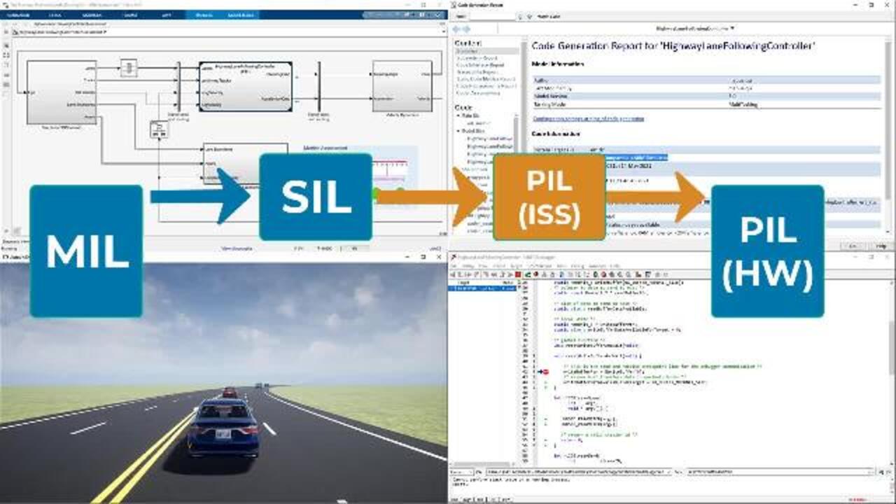
This video has three parts. In the first m we cover PIL testing of software units. Here, we will continue using the instruction set simulator for the RH850 target from previous video. Next, we apply PIL for the same target processor at the integration level. Lastly, we switch the target hardware and compiler toolchain should the need arise.
To this end, we use the ISO 26262 toolkit study from the IEC Certification Kit throughout the video. This case study contains a highway lane following application, spanning engineering activities from requirement specification to the verification of embedded software, and comes with a live script that guides you throughout these activities. We start the case study by typing the following in MATLAB.
So let's start with the first part on unit testing. From the live script, we quickly navigate to functional testing of software units. Then this hyperlink opens the test file for dynamic testing of the controller mode selector unit. The test cases in this file run in model the loop or mail by default.
Let's execute the first requirement based test as is for now. The model passes the test successfully, and shows model coverage as part of the results.
Note that the achieved coverage shows the saturation block is not fully exercised during this test. This is because the input values never exceed the block's limit value. To enhance coverage, additional test cases are needed.
Let's execute the second test case, which helps to achieve full model coverage. Complete functional and structural coverage conclude the verification of this model.
To run the same test case in PIL, we first configure the model for the target hardware and target compiler toolchain. Let's open the model of the system under test. Find Model Settings under the Modeling tab. Notice that we have a reference configuration for parameters associated with this model.
In fact, this project has a data dictionary with this name that contains the project specific configuration parameters. This means that any change to this data dictionary would affect all design models that reference it. To modify the reference configuration, press on the gear icon.
Here are screenshots of the changes we made. You can achieve the same by following the steps detailed in the previous video. We saved that dictionary from within the external data under the Model Explorer so that our changes take effect globally in the project.
Now we are ready to perform build simulations for this and other models in the project. Let's first try to confirm the target connectivity using the SIL/PIL app. Choose PIL mode, then run Verification.
As expected, running in PIL causes MULTI Debugger to start to handle the communication with Simulink. Let's get back to the test file of the Controller Mode Selector and confirm the test case is set to run in PIL. Hit Run.
This performs the requirements-based test case in PIL mode. The results show that the test case has passed the baseline criteria. Additionally, Simulink coverage collects code coverage for this test case. Similar to the model coverage results, we observe that the code that traces back to the saturation block is not fully exercised and for the same reasons.
Let's run the second test case to enhance coverage. The achieved full functional and structural coverage concludes verification of this unit. It is important to note here that running the same tests in MIL and PIL is a form of back-to-back testing. Successfully passing the tests in MIL and PIL against the same expected baseline values validates the numerical equivalence between the model and the target object code.
When you try built this thing, you may notice some increase in the time needed to execute your tests. This is expected as PIL simulation requires communication of the input and outputs of the system under the PIL test. Such communication takes place between Simulink and the code that runs on emulated hardware at each simulation step.
This has some impact on simulation time. You can use hardware in the loop or HIL simulation to get real-time simulations on target.
After performing PIL at the software unit level, let's see how PIL testing and the integration level is no different. The ISO 26262 case study comes with an assessment model that tests the fully integrated software component of the Highway Lane Following system in a closed loop simulation, including a model of the external environment and the model for vehicle dynamics.
Of the assessment model elements, only the controller is part of the embedded software. The case study also has a test file that performs scenario-based testing of the controller.
Let's choose one scenario and the chain simulation mode to PIL. As expected, Simulink establishes the connection through MULTI to the instruction set simulator. Other blocks in the assessment model still run in Simulink. It is noteworthy here to remember that we did not need to configure this model for PIL since PIL configuration is set globally for the project using the reference configuration set.
At integration level, you selectively choose the unit or component you want to run in PIL. Let's go back to the assessment model and navigate inside the controller. Let's set the simulation mode of this reference model to PIL.
Let's execute the test case in normal mode. As expected, the whole assessment model runs in MIL except the block we selected earlier, as you can see here. This concludes integration testing using PIL.
Now, what if the target hardware for your project changes, let's say, from our RH850 to ARM Cortex M7? All you need to do is to establish a new connection between Simulink and MULTI IDE for the new target and link your MULTI IDE installation with the new target compiler toolchain. To do this, close all MULTI windows and execute the following command to link to the ARM target toolchain.
Now, repeat the steps to set up the connection between Simulink and MULTI IDE. First, create a new connection in MULTI for the new instruction set simulator.
Second, set up the connection from the Simulink side. This time, we need to choose a special board and a special anti-file to pass to the linker. You can get this file and other board-specific flags from MULTI IDE by creating a simple project for your target of choice.
Third, configure code generation for the new target on any model in the project. Let's now perform PIL testing for the fully integrated Highway Lane Following system using the new ARM target. As you can see, this works for the new target as well.
In summary, the Simulink family of products offers several capabilities to streamline your in-the-loop testing-- safety standards, like ISO 26262, IEC 61508, or any of its derivatives required to perform adequate testing on the physical target processor. Using Simulink and the MULTI Toolbox, you can directly move from MIL testing to PIL on target hardware. And this will be the subject of another video in the series.
However, you can expect the few surprises when you test on the physical target after testing with instruction set simulators. This incremental approach accelerates development and testing and enhances agility, since instruction sets simulators do not require any additional setup beyond the development host.
Please also note that functional safety standards require evidence to justify the confidence given to software tools. Qualification and certification artifacts from Simulink and MULTI can help you provide this evidence for PIL testing on physical hardware as well as for instruction set simulators.
To get started, fire up Simulink and MULTI IDE and perform PIL testing with your target hardware of choice. Happy testing.
Related Products
Learn More

Featured Product
Embedded Coder


Select a Web Site
Choose a web site to get translated content where available and see local events and offers. Based on your location, we recommend that you select: United States.
You can also select a web site from the following list
Americas
- América Latina (Español)
- Canada (English)
- United States (English)
Europe
- Belgium (English)
- Denmark (English)
- Deutschland (Deutsch)
- España (Español)
- Finland (English)
- France (Français)
- Ireland (English)
- Italia (Italiano)
- Luxembourg (English)
- Netherlands (English)
- Norway (English)
- Österreich (Deutsch)
- Portugal (English)
- Sweden (English)
- Switzerland
- United Kingdom (English)