Working with Digital Inputs and Outputs on STM32 Using Simulink
From the series: Getting Started with STM32 Nucleo Boards Using Simulink
Follow a step-by-step guide on how to design a model in Simulink® using the digital input and output ports on a STM32 Nucleo board. It includes an example of how to make the onboard user LED blink as well as how to use the onboard Push Button to toggle the LED. It also explains the concepts of connected IO and external mode connection with the hardware using Model-Based Design.
To learn more about how to install Simulink Coder Support Package for STMicroelectronics Nucleo Boards watch:
Install Simulink Coder Support Package for STM32 Nucleo Boards (2:25)
Published: 5 Jul 2022
Hello, everyone. This is Jayakarthigeyan Prabakar here from MathWorks. In this video, you will learn how to design a model in Simulink from scratch to use the digital output and digital input ports on the STM32 Nucleo hardware board. We will also learn about the connected IO mode and the external mode to run the Simulink model on the hardware board.
Before we get started, you will need MATLAB release 2016b audible with Simulink installed in your PC. In this video, I'll be using the release 2022a. You should also have installed Simulink Coder Support Package for STMicroelectronics Nucleo Boards. If you want to learn more about how to install the Simulink Coder Support Package for STMicroelectronics Nucleo boards, please refer to the link in the description of this video. Make sure you have a Nucleo board that is supported by the support package. You can see the full list of hardware supported by a particular support package in the MATLAB documentation.
To get started, open Simulink. Create a blank model and save the model with the name of your choice. I'll be calling it Digital_IO. Once you have created the Simulink model, let's bring in the first block that's going to be a pulse generator and we will also add a scope block to check the output of it. If you double-click on the block, it will open the Block Parameters window where you can configure the block with various different parameters. To get more information about each of these parameters specific to a block, click on the Help button. In the Help page, you will be able to get all the details for a specific block.
As you can see, the default parameters is set to 10-second Period and 5% of Pulse Width. So the signal will be an amplitude of value 1 for 0.5 seconds and a value of 0 for the remaining 9.5 seconds in the total time period of 10 seconds. Let's run the simulation to check this in the output of the Scope plot. You will see that for 4.5 seconds, the value is 1 followed by 0 for the rest of the 9.5 seconds.
Now, I'll change the parameter of the Period to 2 and the Pulse Width to 50%. Let me set the Stop Time of the simulation to infinity and rerun the simulation. Now, you'll see that it's generating a train of high and low pulses, which we can give as input to the digital port of the hardware device to turn on and turn off an LED connected to that port.
To do this, let's replace this code block with digital write block. You can either search directly the digital write or open the Simulink Library Browser. Once you open the Simulink Library Browser, on the left side, you will find the list of installed libraries in your version. And on the right side, it will show the blocks available for that specific library.
Like in , Simulink Encoder Support Package for STMicroelectronics Nucleo boards is having the various blocks that are related to it. In the Common section, you'll find the Digital Write, Digital Read, and Analog Input blocks, which are common to multiple STM32 Nucleo boards that are supported by Simulink. And there are hardware-specific blocks for specific purposes.
For now, let's use the digital write block. Connect the output signal of the pulse generator to the input of the digital write block. Let's configure the digital write block with the pin configuration.
Open the digital write block and view pin map. You can see that on-board LED is tagged as LED1 for the STM Nucleo board. Let's enter this value on the digital write block. Alternatively, you can also use D13 or PA_phi as the tags. Let's apply and click OK.
Before we run the simulation, we need to configure this model for the specific hardware that we are going to use. To do this, click on the Modeling tab, select Model Settings, and under Hardware Implementation pane, select the hardware of your choice. In my case, it's going to be the STM32 Nucleo 401RE board. Then under the Target Hardware Resources, you have to enter the COM port of the hardware that has to be used for the connected I/O in external mode. We will understand more why we are entering this COM port value later in the video.
To find the COM port of the hardware that you are connecting to your PC, first connect the hardware to the PC and go to Device Manager. Under Ports, you can find the COM port of your hardware. In my case, it's COM4 the Nucleo board that I have. Let's enter this value. Once you have set this, you will see that there is a new tab called Hardware with the selected hardware board. As you can see there are two modes that you can select. One is Run On Board, also called as External Mode, and the other is connected IO, which is also called as Inputs/Outputs Mode.
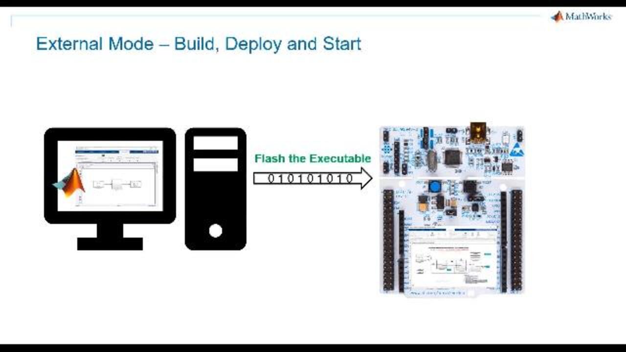
Simulink enables you to run this model with the hardware in three different ways-- connected IO; external mode, monitor and tune; external mode, build, deploy, and start. Let's try external mode. Click on Build Deploy and Start. You'll find two options again, which is Build and Build Deploy and Start. The build-only option generates the code and compiles it for the hardware that you have selected. But it does not deploy the code on the hardware device. But the Build Deploy and Start generates the code, and creates the executable, and flashes it on the hardware device, and starts it.
Click on Build Deploy and Start You can see that the Simulink gets started generating code. Then it is going to deploy it on the hardware. You can see more information in the view diagnostics. Once a model is deployed that is flashed, you can see the LED has started blinking on the hardware. Now, even when you unplug the device and plug it back, it's going to run the same application that was flashed on the device last time.
The other option, which we discussed, is running the module on the hardware in real-time with monitor and tune. Here Simulink generates a code for the model with some additional piece of code that is inserted to vary the parameters of the blocks in real-time to tune the model and to achieve better results for rapid prototyping. Let's try this option now.
When you click on Monitor and Tune, it is going to generate the code and deploy it on the hardware. Now, the code has been deployed on the hardware and it is running in real-time. But it lets us change the parameters of the block.
For example, you can open the Pulse Generator block and change it to pulses of 2 seconds high and 2 seconds low by increasing the time period. When you click on Apply, you can see the changes happening in real-time. You can now see that the LED is blinking for 2 seconds high and 2 seconds low. Now, we will change it back to same as how it was previously with 1 second high and 1 second low.
In the monitor and tune option, when you stop the monitor and tune, the code stops running on the hardware. And when you unplug the device and plug it back in, it does not run the previous code that was flashed on the device, unlike how it happened with build, deploy, and start.
Now, let's try Connected IO. In this mode, Simulink deploys a hardware-specific Connected IO server application on the hardware board and then runs the model on the host PC. Whenever IO peripheral input and output signals have to be used, Simulink exchanges this data from the hardware through the Connected IO server application running on the hardware via serial communication. This is the reason why we had to enter the values of COM port for external mode and Connected IO in the hardware target resources while configuring the model for the specific hardware that we are going to use.
To run the device in this mode, first click on the dropdown on Run with IO. Select Simulation Pacing and enable pacing to slow down simulation. This slows down the simulation running on the host PC to match with the IO server application running on the hardware.
Then click on Run with IO. As you can see in the Diagnostic window, Simulink is updating the server code on the board. Once the server code is deployed on the hardware, you can see that the blinking has started. Now, you can try changing the values in the Pulse Generator to see the changes in the blinking duration.
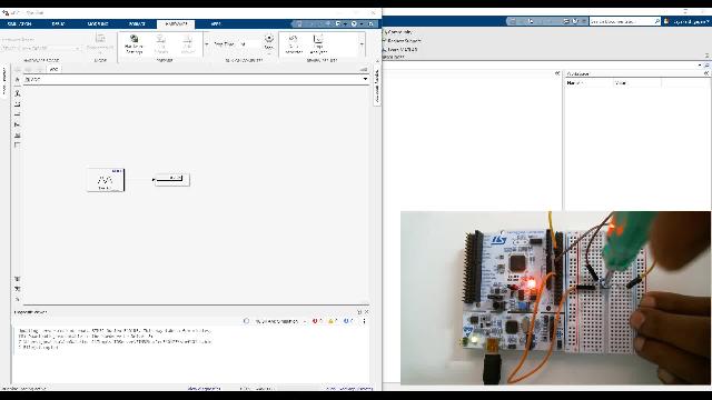
Now that we have successfully used the Digital Write block, we will learn how to use the Digital Read block with the hardware. Let's bring in the Digital Read block into the model. Let me delete the Pulse Generator and connect the Digital Read block to the Digital Write block.
We will configure the Digital Read pin configuration. Let us use the User button provided on the hardware as input. Mention the tag in the Block Configuration window and apply. so now, the signal that is read by the Digital Read block from the User button on the board will be given a signal to the Digital Write block to light up the LED.
Let us see this in action by running the model on the hardware. As you can see, whenever I press the User button, the LED goes off. And when I leave it, the LED It turns on again. Now, if you introduce a NOT operator between the signal line and run the model, it will invert the signal. That is, when you press the button, the LED goes on, and when you leave it, it goes off, which is basically the opposite of what was happening before we introduced the NOT operator.
You can also visualize these signals in the data inspector. To do that, stop the model and select Log Signals on the signal that you would like to visualize. Now that we have selected these signals, let's rerun the model again. And once the model starts running, open the data inspector and select the signal that you want to visualize.
To learn more about how the Simulink data inspector works, I recommend you read the documentation of the same. So with that, we come to the conclusion of this video where you have learned about how to use the Digital Read and Digital Write blocks to work with the digital input and digital outputs. To learn more about how to use other blocks associated with Simulink Support Package for STMicroelectronics Nucleo boards, please look at the Description section of this video. You can learn more about ADC, ISR, and other blocks in the upcoming videos. Thank you for watching.


Select a Web Site
Choose a web site to get translated content where available and see local events and offers. Based on your location, we recommend that you select: United States.
You can also select a web site from the following list
Americas
- América Latina (Español)
- Canada (English)
- United States (English)
Europe
- Belgium (English)
- Denmark (English)
- Deutschland (Deutsch)
- España (Español)
- Finland (English)
- France (Français)
- Ireland (English)
- Italia (Italiano)
- Luxembourg (English)
- Netherlands (English)
- Norway (English)
- Österreich (Deutsch)
- Portugal (English)
- Sweden (English)
- Switzerland
- United Kingdom (English)