5G NR Uplink with PUCCH Vector Waveform Generation
This example shows how to configure and generate a 5G NR uplink vector waveform with physical uplink control channel (PUCCH) for a baseband component carrier by using the nrWaveformGenerator function.
Introduction
This example shows how to parameterize and generate a 5G new radio (NR) waveform for multiple user equipment (UE) transmissions of uplink control by using the nrWaveformGenerator function. The baseband component carrier waveform in this example is characterized by multiple subcarrier spacing (SCS) carriers and bandwidth parts (BWP), and multiple sequences of PUCCH transmission instances and their demodulation reference signals (DM-RS) over the different BWPs. Each sequence of PUCCH models a separate UE transmission. For an example on how to generate a 5G uplink waveform with physical uplink shared channel (PUSCH) and sounding reference signal (SRS), including Release 16 CG-UCI and SRS for positioning, see 5G NR Uplink Vector Waveform Generation.
The example configures multiple sequences of PUCCH for several formats. This figure shows the characteristics of each PUCCH format, as defined in TS 38.211 Section 6.3.2.

Waveform and Carrier Configuration
Use the nrULCarrierConfig object to parameterize baseband waveform generation. This object contains a set of additional objects associated with the waveform channels and signals and enables you to set these uplink carrier configuration parameters.
Label for this UL carrier configuration
SCS carrier bandwidth in resource blocks
Carrier cell ID
Length of the generated waveform in subframes
Windowing
Sample rate of the OFDM-modulated waveform
Carrier frequency for symbol phase compensation
You can control SCS carrier bandwidths and guardbands using the NStartGrid and NSizeGrid properties of the nrSCSCarrierConfig object.
waveconfig = nrULCarrierConfig;    % Create an uplink carrier configuration object
waveconfig.Label = 'UL carrier 1'; % Label for this uplink waveform configuration
waveconfig.NCellID = 0;            % Cell identity
waveconfig.ChannelBandwidth = 40;  % Channel bandwidth (MHz)
waveconfig.FrequencyRange = 'FR1'; % 'FR1' or 'FR2'
waveconfig.NumSubframes = 10;      % Number of 1 ms subframes in generated waveform (1, 2, 4, 8 slots per 1 ms subframe, depending on SCS)
waveconfig.WindowingPercent = 0;   % Percentage of windowing relative to FFT length
waveconfig.SampleRate = [];        % Sample rate of the OFDM-modulated waveform
waveconfig.CarrierFrequency = 0;   % Carrier frequency in Hz. This property is used for symbol phase
                                   % compensation before OFDM modulation

% Define a set of SCS specific carriers, using the maximum sizes for a
% 40 MHz NR channel. See TS 38.101-1 for more information on defined
% bandwidths and guardband requirements.
scscarriers = {nrSCSCarrierConfig,nrSCSCarrierConfig};
scscarriers{1}.SubcarrierSpacing = 15;
scscarriers{1}.NSizeGrid = 216;
scscarriers{1}.NStartGrid = 0;

scscarriers{2}.SubcarrierSpacing = 30;
scscarriers{2}.NSizeGrid = 106;
scscarriers{2}.NStartGrid = 1;
BWPs
A BWP is formed by a set of contiguous resources sharing a numerology on a given SCS carrier. You can define multiple BWPs using a cell array. Each element in the cell array of nrWavegenBWPConfig objects defines a BWP. For each BWP, you can specify the SCS, the cyclic prefix (CP) length, and the bandwidth. The SubcarrierSpacing property links the BWP to one of the SCS-specific carriers defined earlier. The NStartBWP property controls the location of the BWP in the carrier, relative to point A. NStartBWP is expressed in common resource blocks (CRB) in terms of the BWP numerology. Different BWPs can overlap with each other.
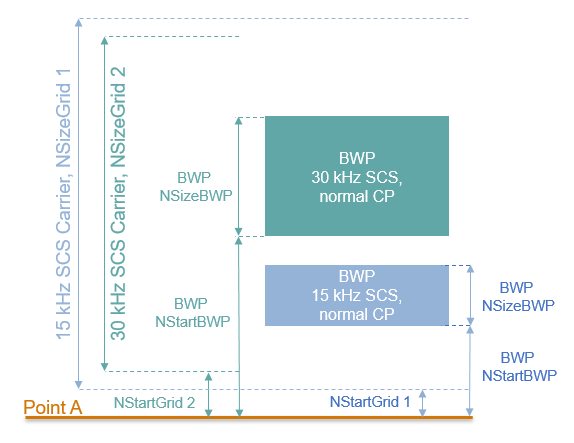
% BWP configurations
bwp = {nrWavegenBWPConfig,nrWavegenBWPConfig};
bwp{1}.BandwidthPartID = 1;        % BWP ID
bwp{1}.Label = 'BWP 1 @ 15 kHz';   % Label for this BWP
bwp{1}.SubcarrierSpacing = 15;     % BWP subcarrier spacing
bwp{1}.CyclicPrefix = 'Normal';    % BWP cyclic prefix for 15 kHz
bwp{1}.NSizeBWP = 25;              % Size of BWP in PRBs
bwp{1}.NStartBWP = 10;             % Position of BWP, relative to point A, in CRBs

bwp{2}.BandwidthPartID = 2;        % BWP ID
bwp{2}.Label = 'BWP 2 @ 30 kHz';   % Label for this BWP
bwp{2}.SubcarrierSpacing = 30;     % BWP subcarrier spacing
bwp{2}.CyclicPrefix = 'Normal';    % BWP cyclic prefix for 30 kHz
bwp{2}.NSizeBWP = 51;              % Size of BWP in PRBs
bwp{2}.NStartBWP = 40;             % Position of BWP, relative to point A, in CRBs
PUCCH Instances Configuration
There are five different formats of PUCCH, each one for different control purposes. Use these format-specific configuration objects to define a sequence of PUCCH instances.
This section specifies the set of PUCCH transmission instances in the waveform by using a cell array. Each element in the cell array defines a sequence of PUCCH transmission instances and must be one of the objects listed above. This example defines three PUCCH sequences that model three UE transmissions: a PUCCH format 3, a PUCCH format 2, and a PUCCH format 0. Some of the properties assigned in this section only apply to certain PUCCH formats. For a list of all properties for a specific format, see the documentation of the PUCCH configuration object for that format.
General Parameters
Set these parameters, common to all formats, for each PUCCH sequence.
Enable or disable this PUCCH sequence
Specify a label for this PUCCH sequence
Specify the BWP carrying the PUCCH. The PUCCH uses the SCS specified for this BWP
Power scaling in dB
pucch = {nrWavegenPUCCH3Config};                   % Create a PUCCH format 3 configuration object for the first UE
pucch{1}.Enable = 1;                               % Enable PUCCH sequence
pucch{1}.Label = 'UE 1 - PUCCH Format 3 @ 15 kHz'; % Label for this PUCCH sequence
pucch{1}.BandwidthPartID = 1;                      % BWP of PUCCH transmission
pucch{1}.Power = 0;                                % Power scaling in dB
Set these format-specific parameters for each PUCCH sequence.
Modulation scheme.
Frequency hopping configuration.
Resource block offset for second hop.
Group hopping configuration.
PUCCH hopping identity. The value is used in sequence generation for format 0, both sequence and DM-RS generation for format 1, and only for DM-RS generation for formats 3 and 4.
RNTI.
NID for scrambling the uplink control information (UCI) bits.
pucch{1}.Modulation = 'QPSK';            % 'pi/2-BPSK','QPSK'
pucch{1}.FrequencyHopping = 'intraSlot'; % Frequency hopping configuration
pucch{1}.SecondHopStartPRB = 10;         % Resource block offset for second hop
pucch{1}.GroupHopping = 'enable';        % Group hopping configuration
pucch{1}.HoppingID = 1;                  % Hopping identity
pucch{1}.RNTI = 11;                      % RNTI for the first UE
pucch{1}.NID = 0;                        % Scrambling identity
Allocation
This figure shows the parameters used in the PUCCH allocation.
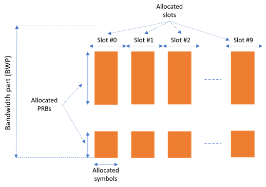
You can set these parameters to control the PUCCH allocation. These parameters are relative to the BWP.
Symbols in a slot allocated to each PUCCH instance. For PUCCH formats 0 and 2, you can only allocate 1 or 2 symbols. For PUCCH formats 1, 3, and 4, you must allocate at least 4 symbols in a slot.
Slots in a frame used for the sequence of PUCCH.
Period of the allocation in slots. Empty period indicates no repetition of the slot pattern.
The allocated PRBs relative to the BWP. For formats 0, 1, and 4, you can only allocate a single PRB.
pucch{1}.SymbolAllocation = [3 11]; % First symbol and length
pucch{1}.SlotAllocation = [3 4];    % Allocated slots indices for PUCCH sequence
pucch{1}.Period = 6;                % Allocation period in slots
pucch{1}.PRBSet = 0:9;              % PRB allocation
PUCCH DM-RS Configuration
You can set these parameters to control the PUCCH DM-RS for each PUCCH sequence.
Presence of additional DM-RS
Additional power boosting for DM-RS
pucch{1}.AdditionalDMRS = 1;        % Additional DM-RS
pucch{1}.DMRSPower = 1;             % Additional power boosting for DM-RS in dB
UCI Payload Configuration
Set these parameters for the UCI payload configuration.
Enable or disable the UCI coding.
Target code rate used to calculate the transport block sizes when both UCI part 1 and UCI part 2 are present.
Number of UCI (HARQ-ACK, SR, and CSI part 1) bits.
Number of UCI part 2 (CSI part 2) bits.
Data source for UCI and UCI part 2. You can use an array of bits or one of these standard PN sequences: 'PN9-ITU', 'PN9', 'PN11', 'PN15', 'PN23'. You can specify the seed for the generator as a cell array in the form {'PN9', seed}. If you do not specify a seed, the generator is initialized with all ones.
pucch{1}.Coding = 1;
pucch{1}.TargetCodeRate = 0.15;
pucch{1}.NumUCIBits = 20;
pucch{1}.NumUCI2Bits = 10;
pucch{1}.DataSourceUCI = 'PN9';
pucch{1}.DataSourceUCI2 = 'PN9';
Specifying Multiple PUCCH Instances
Specify two additional PUCCH sequences for the second BWP. The first one is a PUCCH format 2 that is allocated in the lower end of the second BWP, with no hopping and no repetition. The second sequence is a PUCCH format 0 that is allocated in the top half part of the second BWP and characterized by interslot hopping, 2 UCI bits containing HARQ-ACK, and one scheduling resource (SR) bit.
pucch{2} = nrWavegenPUCCH2Config;                  % Create a PUCCH format 2 configuration object for the second UE
pucch{2}.Label = 'UE 2 - PUCCH Format 2 @ 30 kHz'; % Label for this PUCCH sequence
pucch{2}.BandwidthPartID = 2;                      % PUCCH mapped to 2nd BWP
pucch{2}.SymbolAllocation = [10 2];                % Symbol allocation
pucch{2}.SlotAllocation = 0:2;                     % Slot allocation
pucch{2}.Period = [];                              % Specify no repetitions of the slot pattern for this PUCCH
pucch{2}.RNTI = 12;                                % RNTI for the second UE
pucch{2}.NID0 = 0;                                 % DM-RS scrambling identity

pucch{3} = nrWavegenPUCCH0Config;                  % Create a PUCCH format 0 configuration object for the third UE
pucch{3}.Label = 'UE 3 - PUCCH Format 0 @ 30 kHz'; % Label for this PUCCH sequence
pucch{3}.BandwidthPartID = 2;                      % PUCCH mapped to 2nd BWP
pucch{3}.SymbolAllocation = [1 2];                 % Symbol allocation
pucch{3}.PRBSet = 40;                              % PRB allocation
pucch{3}.FrequencyHopping = 'interSlot';           % Frequency hopping
pucch{3}.SecondHopStartPRB = 30;                   % Resource block offset for second hop
pucch{3}.InitialCyclicShift = 3;                   % Initial cyclic shift
pucch{3}.NumUCIBits = 2;                           % Number of UCI bits containing HARQ-ACK
pucch{3}.DataSourceSR = 1;                         % SR data source
PUSCH Instances Configuration
Specify the set of PUSCH instances in the waveform by using a cell array. Each element in the cell array of nrWavegenPUSCHConfig objects defines a sequence of PUSCH instances. Disable the PUSCH sequence in the first BWP.
pusch = {nrWavegenPUSCHConfig};
pusch{1}.Enable = 0;
pusch{1}.Label = 'PUSCH @ 15 kHz';
pusch{1}.BandwidthPartID = 1;
SRS Instances Configuration
Specify SRS in the waveform. Each element in the cell array of nrWavegenSRSConfig objects defines a sequence of SRS instances associated with a BWP. Disable the SRS sequence in the first BWP.
srs = {nrWavegenSRSConfig};
srs{1}.Enable = 0;
srs{1}.Label = 'SRS @ 15 kHz';
srs{1}.BandwidthPartID = 1;
Waveform Generation
Assign all the channel and signal parameters to the main carrier configuration object nrULCarrierConfig, then generate and plot the waveform.
waveconfig.SCSCarriers = scscarriers;
waveconfig.BandwidthParts = bwp;
waveconfig.PUCCH = pucch;
waveconfig.PUSCH = pusch;
waveconfig.SRS = srs;

% Generate complex baseband waveform
[waveform,info] = nrWaveformGenerator(waveconfig);
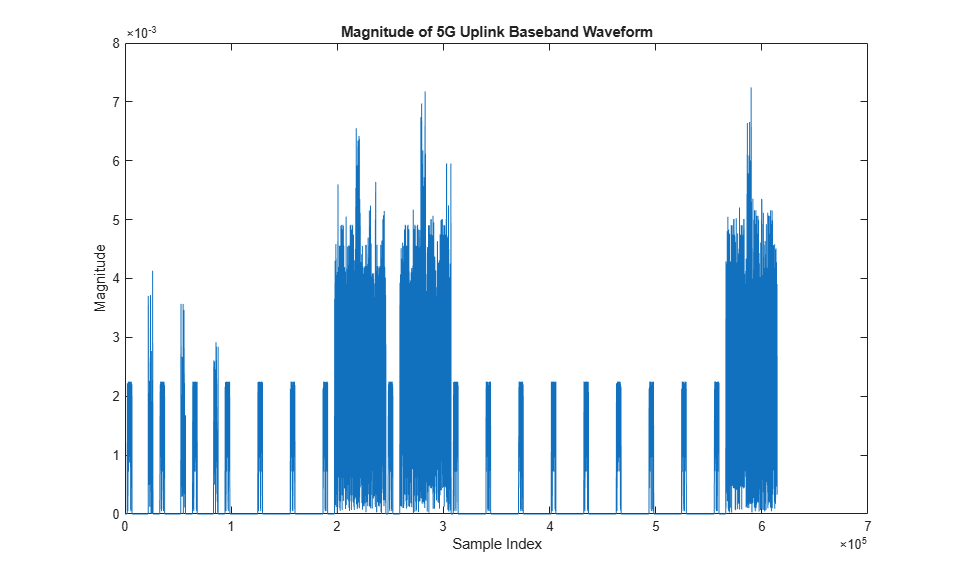
Plot the magnitude of the baseband waveform.
figure;
plot(abs(waveform));
title('Magnitude of 5G Uplink Baseband Waveform');
xlabel('Sample Index');
ylabel('Magnitude');
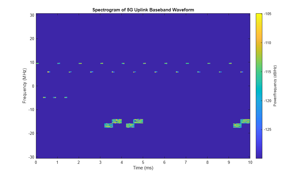
Plot the spectrogram of the baseband waveform. The plot shows the resource allocation of the three PUCCH sequences.
PUCCH format 3, in the first BWP, is in the lower part of the spectrogram. The plot shows intraslot frequency hopping of this PUCCH.
PUCCH format 2, in the second BWP, is around -10 MHz.
PUCCH format 0, in the second BWP, is the central part of the spectrogram. The plot shows interslot frequency hopping of this PUCCH.
samplerate = info.ResourceGrids(1).Info.SampleRate;
nfft = info.ResourceGrids(1).Info.Nfft;
figure;
spectrogram(waveform(:,1),ones(nfft,1),0,nfft,'centered',samplerate,'yaxis','MinThreshold',-130);
title('Spectrogram of 5G Uplink Baseband Waveform');
The waveform generator function returns the time-domain waveform and a structure info. The info structure contains the underlying resource element grid and a breakdown of the resources that all the PUCCH, PUSCH, and SRS instances use in the waveform.
For example, display the high-level information of the first PUCCH.
disp('Information associated with the first PUCCH:')
disp(info.WaveformResources.PUCCH(1))
Information associated with the first PUCCH:
               Name: 'UE 1 - PUCCH Format 3 @ 15 kHz'
    PrecodingMatrix: 1.0000 + 0.0000i
             Format: 3
         CDMLengths: [1 1]
          Resources: [1×3 struct]

The ResourceGrids field is a structure array, which contains these fields.
The resource grid corresponding to each BWP.
The resource grid of the overall bandwidth containing the channels and signals in each BWP.
An info structure with information corresponding to each BWP. For example, display the information for the first BWP.
disp('Modulation information associated with BWP 1:')
disp(info.ResourceGrids(1).Info)
Modulation information associated with BWP 1:
                   Nfft: 4096
             SampleRate: 61440000
    CyclicPrefixLengths: [320 288 288 288 288 288 288 320 288 … ] (1×14 double)
          SymbolLengths: [4416 4384 4384 4384 4384 4384 4384 … ] (1×14 double)
              Windowing: 0
           SymbolPhases: [0 0 0 0 0 0 0 0 0 0 0 0 0 0]
         SymbolsPerSlot: 14
       SlotsPerSubframe: 1
          SlotsPerFrame: 10
                     k0: 0