Electrical Length of Antenna
The physical length of an antenna is the actual physical dimensions of the antenna.
Consider a dipole antenna from the Antenna Toolbox™ with an operating frequency of 75 MHz and corresponding wavelength of 4 m.
The dipole object creates a half-wavelength dipole antenna, hence its
electrical length is Lambda/2 or 2 m, which is equal to the physical length of the
antenna.
The electrical length of an antenna is
where: is the propagation constant dependent on the wavelength , permittivity , and permeability .
is the physical length of the antenna.
You can change the electrical length by changing the physical length and the propagation constant. The propagation constant depends on permittivity, permeability of antenna materials, and operating frequency.
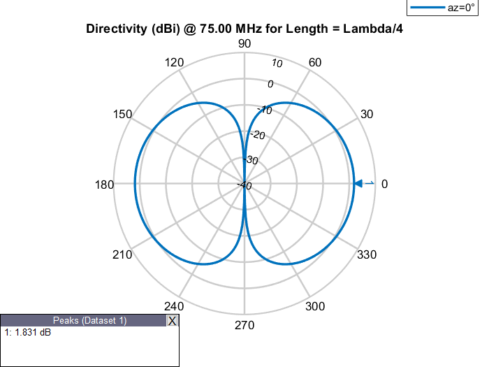
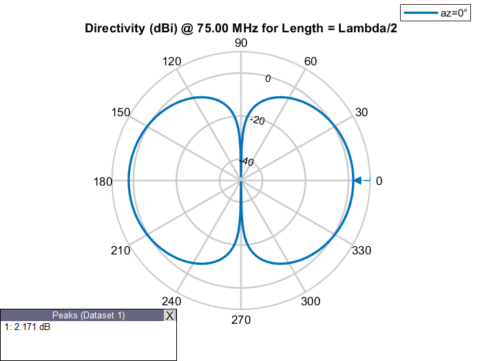
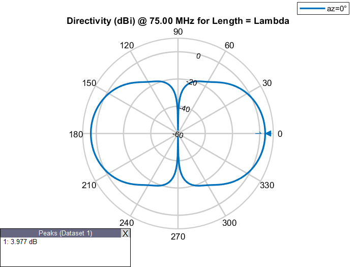
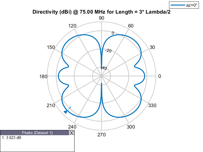
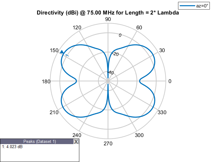
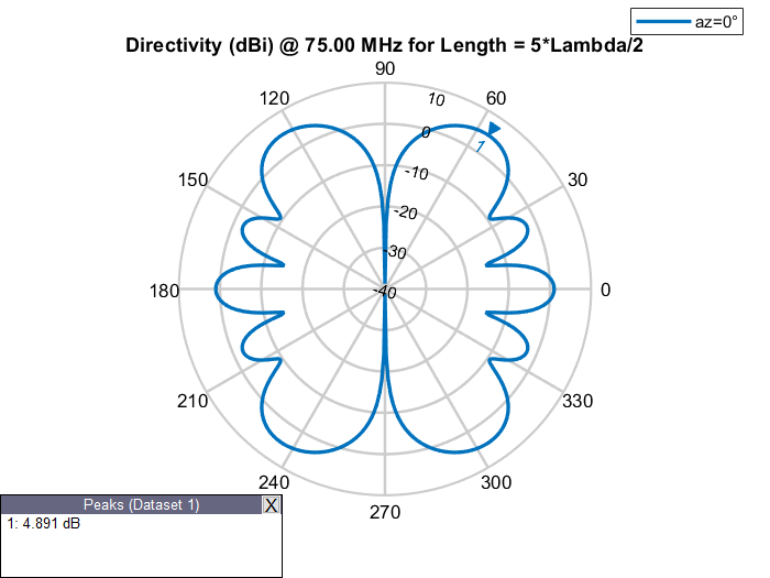
Elevation Patterns of Dipole Antennas
Observe gain of the dipole antennas of various physical lengths at a frequency of 75 MHz in the table below.
Elevation Patterns of Dipole Antennas of Various Physical Lengths at Frequency of 75 MHz
|
|
|
|
|
|
|
|
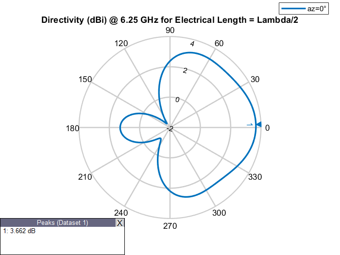
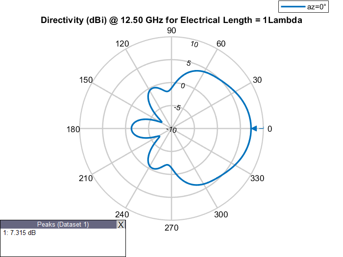
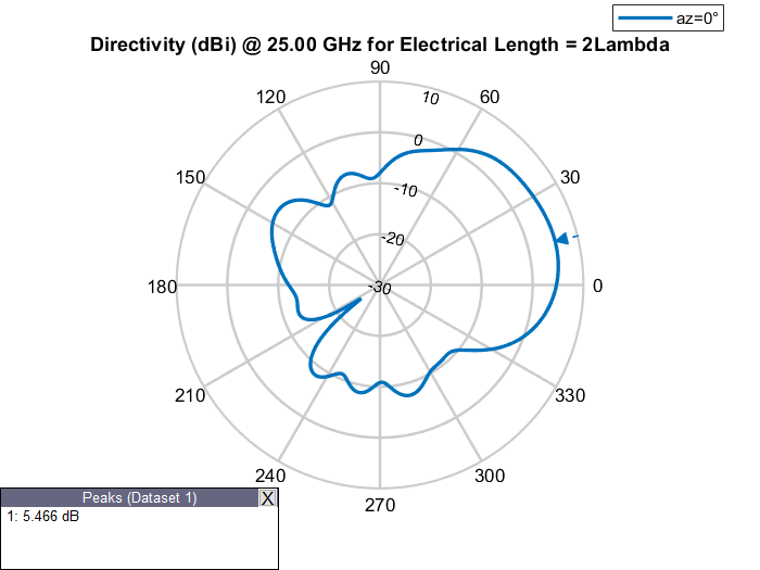
Elevation Patterns of Rectangular Waveguides at Different Frequencies
Design a rectangular WR-90 waveguide with default length of 1
Lambda at an operating frequency of 12.5 GHz. Examine its elevation pattern. Vary
the operating frequency and electrical length of the antenna and examine how the
elevation pattern changes.
Elevation Patterns of Waveguides of Various Electrical Lengths
|
|
|
|
Effect of Materials and Reactance on Electrical Length
Effect of Materials
Increasing the relative permittivity or dielectric constant of a material
increases the propagation constant. Similarly, increasing the relative
permeability of a material also increases the propagation constant. Design two
microstrip patch antennas, one with air as the substrate and
another with a FR4 substrate. Analyze their dimensions at the
same operating frequency.
Compare Dimensions of Microstrip Patch Antennas with Different Substrates
Design a microstrip patch antenna with air as a substrate at a frequency of 1 GHz.
design(patchMicrostrip,1e9)
ans =
  patchMicrostrip with properties:

               Length: 0.1439
                Width: 0.1874
               Height: 0.0030
            Substrate: [1×1 dielectric]
    GroundPlaneLength: 0.2998
     GroundPlaneWidth: 0.2998
    PatchCenterOffset: [0 0]
           FeedOffset: [0.0303 0]
            Conductor: [1×1 metal]
                 Tilt: 0
             TiltAxis: [1 0 0]
                 Load: [1×1 lumpedElement]
Design a microstrip patch antenna with FR4 as a substrate at a frequency of 1 GHz.
design(patchMicrostrip(Substrate=dielectric("FR4")),1e9)ans =
patchMicrostrip with properties:
Length: 0.0664
Width: 0.0855
Height: 0.0014
Substrate: [1×1 dielectric]
GroundPlaneLength: 0.1368
GroundPlaneWidth: 0.1368
PatchCenterOffset: [0 0]
FeedOffset: [0.0140 0]
Conductor: [1×1 metal]
Tilt: 0
TiltAxis: [1 0 0]
Load: [1×1 lumpedElement]
Effect of Antenna Loading
The effective electrical length of an antenna can be changed without changing its physical length by adding reactance, (inductance or capacitance) in series with the antenna. This is called lumped-impedance matching or loading. For example, consider a monopole antenna and a monopole antenna with a top hat of the same physical length. The monopole antenna with a top hat resonates at a lower frequency as compared to the monopole antenna without top hat. Hence, the corresponding wavelength for monopole with a top hat is higher and, its electrical length is larger.
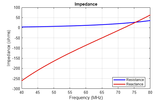
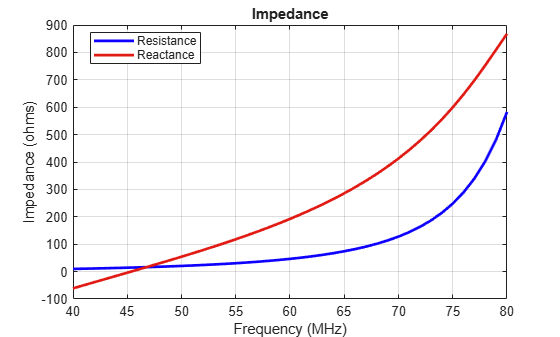
Compare Impedance of Monopole and Top Hat Monopole Antennas
Calculate and plot the impedance of a monopole antenna over a frequency range of 40 MHz-80 MHz.
figure;
impedance(monopole,linspace(40e6,80e6,41))
Calculate and plot the impedance of a top hat monopole antenna over a frequency range of 40 MHz-80 MHz.
figure;
impedance(monopoleTopHat,linspace(40e6,80e6,41))
Mesh at Various Frequencies
Observe meshing of the dipole antennas of same physical lengths at frequencies of 37.5, 75, and 150 MHz in the table below.
Meshing of Dipole Antenna at Various Frequencies
|
|
|
|
| Frequency = 37.5 MHz | Frequency = 75 MHz | Frequency = 150 MHz |
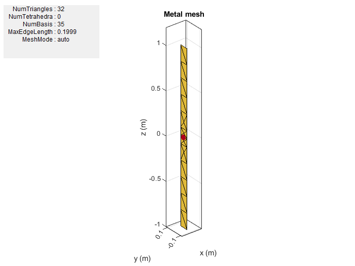
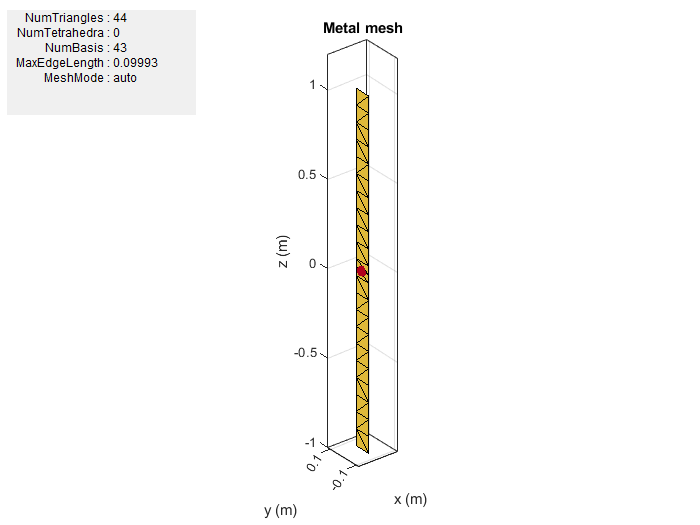

The antenna lengths stay the same, but as the operating frequency of the antenna changes, the number of triangles in the mesh change as do the solutions for the analysis functions.
References
[1] Balanis, C.A. Antenna Theory: Analysis and Design. 3rd Ed. New York: Wiley, 2005.