QPSK Receiver Using Software-Defined Radio
This example shows how to use the Universal Software Radio Peripheral(USRP™) and ADALM-PLUTO device using SDRu and PLUTO Radio System objects to implement a QPSK receiver. The receiver addresses practical issues in wireless communications, such as carrier frequency and phase offset, timing offset and frame synchronization. This system receives the signal sent by the QPSK transmitter at bit rate of up to 1 Mbps. The receiver demodulates the received symbols and prints a simple message to the MATLAB® command line. For more information on designing a QPSK transmitter, see the QPSK Transmitter with Software-Defined Radio (SDR) example.
This example has the following motivation:
To implement a real QPSK-based transmission-reception environment in MATLAB using System objects.
To illustrate the use of key Communications Toolbox™ System objects for QPSK system design, including coarse and fine carrier frequency compensation, timing recovery, frame synchronization, carrier phase ambiguity resolution, and message decoding.
Required Hardware and Software
To run this example, you need one of these USRP or ADALM-PLUTO radios and the corresponding hardware support package.
USRP™ N2xx series or B2xx series radio and Communications Toolbox Support Package for USRP Radio. For more information, see USRP Radio and Supported Hardware and Required Software.
USRP™ E320, N3xx, X3xx, or X4xx series radio and Wireless Testbench Support Package for NI USRP Radios. For more information, see Supported Radio Devices (Wireless Testbench).
ADALM-PLUTO radio and Communications Toolbox Support Package for Analog Devices® ADALM-PLUTO Radio. For more information, see ADALM-Pluto Radio.
Initialization
Select Radio
Select the required radio SDRName from the availableRadios table. For more information regarding discovery of radios see, findsdr.
selectSDRType ="USRP"; availableRadios = findsdr(SDRType=selectSDRType, StatusType="RxAvailable")
Checking radio connections ...
availableRadios=1×4 table
    "B200"    "USRP"    "F5BC9E"    true
SDRName ="B200"; SDRAddress =
"F5BC9E";
Clear the MATLAB workspace whenever you modify the SDRs.
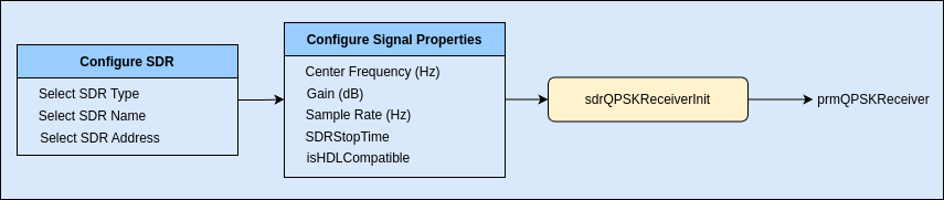
Initialize Receiver Parameters
The sdrQPSKReceiverInit.m script initializes the simulation parameters and generates the structure prmQPSKReceiver.
QPSK Receiver Parameters
sampleRate =1000000; isHDLCompatible =
true; % disable to run 'FFT-Based' coarse frequency compensation instead of 'Correlation-Based' for improved performance in MATLAB version.
SDR Parameters
SDRGain =25; SDRCenterFrequency =
915000000; SDRStopTime =
10;
Display received data
previewReceivedData =true; % enable to preview the received data printReceivedData =
false; % enable to print the received data
Receiver parameter structure
prmQPSKReceiver = sdrQPSKReceiverInit(SDRName, SDRAddress, sampleRate, SDRCenterFrequency, ...
    SDRGain, SDRStopTime, isHDLCompatible, availableRadios)
prmQPSKReceiver = struct with fields:
Fs: 1000000
ModulationOrder: 4
Interpolation: 2
Decimation: 1
Rsym: 500000
Tsym: 2.0000e-06
CFCAlgorithm: 'Correlation-Based'
BarkerCode: [1 1 1 1 1 -1 -1 1 1 -1 1 -1 1]
BarkerLength: 13
HeaderLength: 26
Message: 'Hello world'
MessageLength: 16
NumberOfMessage: 100
PayloadLength: 11200
FrameSize: 5613
FrameTime: 0.0112
RolloffFactor: 0.5000
ScramblerBase: 2
ScramblerPolynomial: [1 1 1 0 1]
ScramblerInitialConditions: [0 0 0 0]
RaisedCosineFilterSpan: 10
DesiredPower: 2
AveragingLength: 50
MaxPowerGain: 60
MaximumFrequencyOffset: 6000
PhaseRecoveryLoopBandwidth: 0.0100
PhaseRecoveryDampingFactor: 1
TimingRecoveryLoopBandwidth: 0.0100
TimingRecoveryDampingFactor: 1
TimingErrorDetectorGain: 5.4000
PreambleDetectionThreshold: 0.8000
BerMask: [7700×1 double]
Platform: "B200"
Address: "F5BC9E"
IsPluto: 0
IsRadioRxAvailable: 1
MasterClockRate: 20000000
USRPCenterFrequency: 915000000
USRPGain: 25
USRPFrontEndSampleRate: 1000000
USRPDecimationFactor: 20
USRPFrameLength: 11226
SDRFrameTime: 0.0112
StopTime: 10
Note:
To receive successfully, ensure that the specified center frequency of the receiver system objects is within the acceptable range of the selected RF card.
Enable either
previewReceivedDataorprintReceivedData, enabling both will show only preview of received data.
Code Architecture
The function runSDRQPSKReceiver implements the QPSK receiver using two System objects,
Either
comm.SDRuReceiverfor USRP orcomm.SDRRxPlutofor ADALM-PLUTO.QPSKReceiverfor decoding received data.
USRP/PLUTO Receiver
The host computer communicates with the USRP radio using comm.SDRuReceiver and with the ADALM-PLUTO radio using the comm.SDRRxPluto System object.
QPSK Receiver
This component regenerates the original transmitted message. It is divided into six subcomponents, modeled using System objects. Each subcomponent is modeled by other subcomponents using System objects.
Automatic Gain Control: Sets its output power to a level ensuring that the equivalent gains of the phase and timing error detectors keep constant over time. The AGC is placed before the Raised Cosine Receive Filter so that the signal amplitude can be measured with an oversampling factor of two. This process improves the accuracy of the estimate.
Coarse frequency compensation: Uses a correlation-based algorithm to roughly estimate the frequency offset and then compensate for it. The estimated coarse frequency offset is averaged so that fine frequency compensation is allowed to lock/converge. Hence, the coarse frequency offset is estimated using a
comm.CoarseFrequencyCompensatorSystem object and an averaging formula; the compensation is performed using acomm.PhaseFrequencyOffsetSystem object.Timing recovery: Performs timing recovery with closed-loop scalar processing to overcome the effects of delay introduced by the channel, using a
comm.SymbolSynchronizerSystem object. The object implements a PLL to correct the symbol timing error in the received signal. The rotationally-invariant Gardner timing error detector is chosen for the object in this example; thus, timing recovery can precede fine frequency compensation. The input to the object is a fixed-length frame of samples. The output of the object is a frame of symbols whose length can vary due to bit stuffing and stripping, depending on actual channel delays.Fine frequency compensation: Performs closed-loop scalar processing and compensates for the frequency offset accurately, using a
comm.CarrierSynchronizerSystem object. The object implements a phase-locked loop (PLL) to track the residual frequency offset and the phase offset in the input signal.Frame Synchronization: Performs frame synchronization and, also, converts the variable-length symbol inputs into fixed-length outputs, using a
FrameSynchronizerSystem object. The object has a secondary output that is a boolean scalar indicating if the first frame output is valid.Data decoder: Performs phase ambiguity resolution and demodulation. Also, the data decoder compares the regenerated message with the transmitted one and calculates the BER.
Execution and Results
To ensure data reception, first start the QPSK Transmitter with Software-Defined Radio example.
if prmQPSKReceiver.IsRadioRxAvailable
    [BER, overflow, output] = runSDRQPSKReceiver(prmQPSKReceiver, previewReceivedData, printReceivedData);

    fprintf('Error rate is = %f.\n', BER(1));
    fprintf('Number of detected errors = %d.\n', BER(2));
    fprintf('Total number of compared samples = %d.\n', BER(3));
    fprintf('Total number of overflows = %d.\n', overflow);
else
    fprintf('The receiver of the radio with address, %s, is not available.\n', SDRAddress);
end
Hello world 000
Hello world 001
Hello world 002
Hello world 003
Hello world 004
Hello world 005
...
...
Show all messages
Error rate is = 0.000033.
Number of detected errors = 229.
Total number of compared samples = 6845300.
Total number of overflows = 1.
Note: Before running the example, first connect the selected SDRName to the computer and turn it on.
When you run the experiments, the received messages are decoded and preview of the received data is shown. BER information is also shown at the end of the script execution. The receiver calculates the BER value even when some of the adaptive components are not converged. This results in a high BER value. Once the transient period is over, the receiver is able to estimate the transmitted frame and the BER dramatically decreases. In this example, to guarantee a reasonable execution time of the system in simulation mode, the simulation duration is fairly short. As such, the overall BER results are significantly affected by the high BER values at the beginning of the simulation. To increase the simulation duration and obtain lower BER values, you can change the SDRStopTime.
Troubleshooting
The gain behavior of ADALM-PLUTO and different USRP RF cards varies considerably. Thus, the gain setting in the transmitter and receiver defined in this example may not be well-suited for your RF cards. If the message is not properly decoded by the receiver system, you can vary the gain of the source signals in the SDR Transmitter and SDR Receiver System objects by changing the SDRGain value.
Preamble detector's threshold also affects the decoded message. If you see recurrent garbled messages, please try to increase the preamble detector's threshold as the following steps are trying to decode the header. If you cannot see any output message, try to decrease the threshold in the receiver initialization file.
A large relative frequency offset between the transmit and receive USRP radios can prevent the receiver functions from properly decoding the message. If that happens, you can determine the offset by sending a tone at a known frequency from the transmitter to the receiver, then measuring the offset between the transmitted and received frequency, then applying that offset to the SDRCenterFrequency of the receiver System object. You increase the frequency offset value in the receiver initialization file to estimate the maximum possible frequency offset at the receiver.
Helper Functions
sdrQPSKReceiverInit.mrunSDRQPSKReceiver.mQPSKReceiver.mQPSKDataDecoder.mFrameSynchronizer.m
References
[1] Rice, Michael. Digital Communications - A Discrete-Time Approach. 1st ed. New York, NY: Prentice Hall, 2008.