CrossSectionNode
Description
The CrossSectionNode object represents a node in a
cross-section profile. A cross-section profile consists of nodes connected by a sequence of
parametric spans. Each node in the span sequence marks a specific location across the road at
a certain distance, measured relative to the left edge of the road. Use this object to control
cross-section height variations along the width of the road.
Creation
To retrieve the CrossSectioneNode objects from a cross-section curve in
your RoadRunner scene, extract the Nodes property of the corresponding
CrossSectionCurve object. For
example, crossSectionNodes = CrossSectionCruve1.Nodes extracts all the
nodes in the cross-section profile CrossSectionCurve1 to the array of
CrossSectionNode objects crossSectionNodes.
Properties
Examples
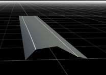
Create a RoadRunner scene with non-uniform height variations across a four-lane road.
Create a roadrunner object, specifying the path to an existing project. For example, this code shows the path to a project, on a Windows® machine, located at "C:\RR\MyProject". This code assumes that RoadRunner is installed in the default location, and returns an object, rrApp, that provides functions for performing basic tasks such as opening, closing, and saving scenes and projects.
rrApp = roadrunner(ProjectFolder="C:\RR\MyProject");Note: If you are opening RoadRunner from MATLAB® for the first time, or if you have changed the RoadRunner installation location since you last opened it from MATLAB, you can use the roadrunnerSetup (RoadRunner) function to specify new default project and installation folders to use when opening RoadRunner. You can save these folders between MATLAB sessions by selecting the Across MATLAB sessions option from the corresponding drop down.
Create a new RoadRunner scene in the current project by using the newScene function, specifying the roadrunner object rrApp.
newScene(rrApp);
Create a roadrunnerAPI object, rrApi, that references the object for the current RoadRunner instance rrApp. The rrApi object enables you to programmatically author scenes, such as by adding and modifying road and lane components, using MATLAB.
rrApi = roadrunnerAPI(rrApp);
Extract the object for your scene from the Scene property of the authoring API object rrApi. The extracted Scene object enables you to specify the scene in which to add scene elements such as roads and lanes.
scn = rrApi.Scene;
Extract the Project object for your RoadRunner project from the Project property of the authoring API object rrApi. The extracted Project object enables you to specify the project folder for the current RoadRunner session from which to retrieve asset objects. You can use the asset objects to assign markings to the lanes in your scene.
prj = rrApi.Project;
Add a horizontal road 100 meters in length to the scene by using the addLineArcRoad function. Specify the position of the road by specifying the positions of its control points along the X- and Y-axes of the RoadRunner local coordinate system. These control points define the positions of the start and end of the road. You can modify the positions of the control points to adjust the length and direction of the road relative to the scene origin. You can also add control points between the start and end points of the line-arc curve to adjust the curvature and radius of the road curve.
rrHorizontalRoad = addLineArcRoad(scn,[0 0; 100 0]);
Extract the reference lane of the road from the ReferenceLane property of the road object rrHorizontalRoad. The reference lane defines the center lane, or reference line, of a road in a RoadRunner scene. This lane has no width and serves as the basis for positioning all other lanes, which RoadRunner arranges outward from the reference line.
refLane = rrHorizontalRoad.ReferenceLane;
Use the getAsset (RoadRunner Scenario) function to extract lane marking style objects, which represent the DashedSingleWhite.rrlms and SolidSingleWhite.rrlms assets, from the project prj. Use these assets to mark the reference lane of the road. You can also use these assets to assign lane‑marking styles to other driving and shoulder lanes.
dashedWhiteMarkingStyle = prj.getAsset("<PROJECT>/Assets/Markings/DashedSingleWhite.rrlms","LaneMarkingStyle");
solidWhiteMarkingStyle  = prj.getAsset("<PROJECT>/Assets/Markings/SolidSingleWhite.rrlms","LaneMarkingStyle");
RferenceLaneSpan = refLane.LaneMarkingProfile.Spans(1);
ReferenceLaneSpan.LaneMarkingStyle = dashedWhiteMarkingStyle;
Add one lane to the left and one to the right of the reference lane by using the addLaneToLeft and addLaneToRight functions. For each lane, specify the lane type and travel direction using the LaneType and TravelDirection properties. Assign the appropriate marking style for each lane by modifying the first span of the marking profile of each lane.
leftLane1 = addLaneToLeft(refLane);
leftLane1.LaneType = "driving";
leftLane1.TravelDirection = "backward";
leftLane1.LaneMarkingProfile.Spans(1).LaneMarkingStyle = solidWhiteMarkingStyle;
rightLane1 = addLaneToRight(refLane);
rightLane1.LaneType = "driving";
rightLane1.TravelDirection = "forward";
rightLane1.LaneMarkingProfile.Spans(1).LaneMarkingStyle = solidWhiteMarkingStyle;
Add shoulder lanes to the driving lanes. Use the addLaneToLeft and addLaneToRight functions to place a shoulder lane on each side. Set their lane types to "shoulder", and configure their width profiles by editing the WidthProfile nodes.
endLane1 = addLaneToLeft(leftLane1);
endLane1.LaneType = "shoulder";
endLane1WidthProfile = endLane1.WidthProfile;
endLane1WidthProfile.Nodes(1).EndWidth   = 1.75;
endLane1WidthProfile.Nodes(2).StartWidth = 1.75;
endLane2 = addLaneToRight(rightLane1);
endLane2.LaneType = "shoulder";
endLane2WidthProfile = endLane2.WidthProfile;
endLane2WidthProfile.Nodes(1).EndWidth   = 1.75;
endLane2WidthProfile.Nodes(2).StartWidth = 1.75;
Define a non-uniform cross‑section height profile for the road by first extracting the lateralProfile property of the road and then extract the CrossSectionCurve property of the lateralProfile object. The first node of the lateralProfile object represents the cross‑section node at the left edge of the road. Insert three intermediate cross‑section nodes into the cross‑section curve of the road at lateral distances of 0.5, 1.5, and 3.0 meters using the insertNode function. Then assign elevation values of 2.0, 3.8, and 1.7 meters to these nodes by setting their Height property of the cross-section nodes to create a non-uniform height variations.
lateralProfile = rrHorizontalRoad.LateralProfile;
lateralProfileNodes = lateralProfile.Nodes;
startNode = lateralProfileNodes(1);
crossSectionProfile = startNode.CrossSectionCurve;
csNode1 = insertNode(crossSectionProfile, 0.5);
csNode1.Height = 2.0;
csNode2 = insertNode(crossSectionProfile, 1.5);
csNode2.Height = 3.8;
csNode3 = insertNode(crossSectionProfile, 3.0);
csNode2.Height = 1.7;
Version History
Introduced in R2026a
See Also
roadrunnerAPI | roadrunnerSetup | getAsset | Scene | Lane | ReferenceLane | addLineArcRoad | LaneMarkingStyle | LateralProfile | CrossSectionCurve | CrossSectionSpan