Allpole Filter
Model allpole filters
Libraries:
DSP System Toolbox /
Filtering /
Filter Implementations
Description
The Allpole Filter block independently filters each channel of the input signal with the specified allpole filter. The block can implement static filters with fixed coefficients and time-varying filters with coefficients that change over time. You can tune the coefficients of a static filter during simulation.
This block filters each channel of the input signal independently over time. The Input processing parameter allows you to specify whether the block treats each element of the input as an independent channel (sample-based processing), or each column of the input as an independent channel (frame-based processing).
This block supports the Simulink® state logging feature. See State (Simulink) for more information.
Examples
Estimate Transfer Function in Simulink
To estimate the transfer function of a system in Simulink®, use the Discrete Transfer Function Estimator block. The block implements the Welch's average modified periodogram method and uses the measured input and output data for estimation.
Ports
Input
Specify the data input as a vector or a matrix. The block accepts variable-size inputs. During simulation, you can change the size of each input channel, but the number of channels must remain the same.
The data input and the filter coefficients must have the same data type.
If the input is fixed point, it must be a signed integer or a signed fixed point value with a power-of-two slope and zero bias.
This port is unnamed until you set Coefficient
source to Input port.
Data Types: single | double | int8 | int16 | int32 | fixed point
Complex Number Support: Yes
Specify the denominator coefficients of the filter transfer function as a scalar or a row vector. The data input and the filter coefficients must have the same data type.
Dependencies
To enable this port, set Coefficient source
to Input port.
Data Types: single | double | int8 | int16 | int32 | fixed point
Complex Number Support: Yes
Output
Filtered output, returned as a vector or a matrix. The size, data type, and complexity of the output signal matches that of the input signal.
This port is unnamed until you set Coefficient
source to Input port.
Data Types: single | double | int8 | int16 | int32 | fixed point
Complex Number Support: Yes
Parameters
Main Tab
Select whether you want to specify the filter coefficients in the block mask or through an input port.
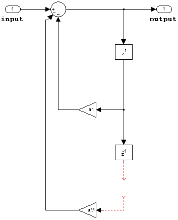
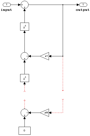
Specify the filter structure as one of these:
Direct formDirect form transposedLattice AR
The block does not support analysis methods for fixed-point processing if you specify
the structure as Direct form or
Direct form transposed.
Specify the denominator coefficients of the filter transfer function as a scalar or a row vector.
Tunable: Yes
Dependencies
To enable this parameter, set Coefficient
source to Dialog
parameters.
Specify whether the block performs sample- or frame-based processing. You can select one of the following options:
Columns as channels (frame based)— Treat each column of the input as an independent channel (frame-based processing).Elements as channels (sample based)— Treat each element of the input as an independent channel (sample-based processing).
Specify the initial conditions of the filter states as a scalar, vector, or a matrix.
The Allpole Filter block initializes the internal filter states to zero by default, which has the same effect as assuming that past inputs and outputs are zero. You can optionally use this parameter to specify nonzero initial conditions for the filter delays.
To determine the number of initial states you must specify and how to specify them, see the table on valid initial states. The Initial states parameter can take one of the forms described in this table.
Valid Initial States
| Initial Condition | Description |
|---|---|
Scalar | The block initializes all delay elements in the filter to the scalar value. |
Vector or matrix | Each vector or matrix element specifies a unique initial condition for a corresponding delay element in a corresponding channel:
|
Data Types Tab
Specify the coefficient data type. You can set it to:
A rule that inherits a data type, for example,
Inherit: Same word length as inputA built-in integer, for example,
int8A data type object, for example, a
Simulink.NumericTypeobjectAn expression that evaluates to a data type, for example,
fixdt(1,16,0)
Click the Show data type assistant button
![]() to display the Data Type
Assistant, which helps you set the
Coefficients parameter.
to display the Data Type
Assistant, which helps you set the
Coefficients parameter.
See Specify Data Types Using Data Type Assistant (Simulink) for more information.
Specify the minimum value of the filter coefficients. The default value is
[] (unspecified). Simulink software uses this value to perform:
Parameter range checking (see Specify Minimum and Maximum Values for Block Parameters (Simulink))
Automatic scaling of fixed-point data types
Specify the maximum value of the filter coefficients. The default value is
[] (unspecified). Simulink software uses this value to perform:
Parameter range checking (see Specify Minimum and Maximum Values for Block Parameters (Simulink))
Automatic scaling of fixed-point data types
Specify the product output data type. You can set it to:
A rule that inherits a data type, for example,
Inherit: Inherit via internal
										rule
. For more information on this rule, see Inherit via Internal Rule.A built-in data type, for example,
int8A data type object, for example, a
Simulink.NumericTypeobjectAn expression that evaluates to a data type, for example,
fixdt(1,16,0)
Click the Show data type assistant button
![]() to display the Data Type
Assistant, which helps you set the Product
output parameter.
to display the Data Type
Assistant, which helps you set the Product
output parameter.
See Specify Data Types Using Data Type Assistant (Simulink) for more information.
Specify the accumulator data type. You can set it to:
A rule that inherits a data type, for example,
Inherit: Inherit via internal
										rule
. For more information on this rule, see Inherit via Internal Rule.A built-in data type, for example,
int8A data type object, for example, a
Simulink.NumericTypeobjectAn expression that evaluates to a data type, for example,
fixdt(1,16,0)
Click the Show data type assistant button
![]() to display the Data Type
Assistant, which helps you set the
Accumulator parameter.
to display the Data Type
Assistant, which helps you set the
Accumulator parameter.
See Specify Data Types Using Data Type Assistant (Simulink) for more information.
Specify the state data type. You can set it to:
A rule that inherits a data type, for example,
Inherit: Same as
									accumulator
A built-in integer, for example,
int8A data type object, for example, a
Simulink.NumericTypeobjectAn expression that evaluates to a data type, for example,
fixdt(1,16,0)
Click the Show data type assistant button
![]() to display the Data Type
Assistant, which helps you set the
State parameter.
to display the Data Type
Assistant, which helps you set the
State parameter.
See Specify Data Types Using Data Type Assistant (Simulink) for more information.
Dependencies
To enable this parameter, set Filter
structure to Lattice
AR.
Specify the output data type. You can set it to:
A rule that inherits a data type, for example,
Inherit: Same as
									accumulator
A built-in data type, for example,
int8A data type object, for example, a
Simulink.NumericTypeobjectAn expression that evaluates to a data type, for example,
fixdt(1,16,0)
Click the Show data type assistant button
![]() to display the Data Type
Assistant, which helps you set the
Output parameter.
to display the Data Type
Assistant, which helps you set the
Output parameter.
See Control Data Types of Signals (Simulink) for more information.
Specify the minimum value that the block must output. The default value is
[] (unspecified). Simulink software uses this value to perform:
Simulation range checking (see Specify Signal Ranges (Simulink))
Automatic scaling of fixed-point data types
Specify the maximum value that the block must output. The default value is
[] (unspecified). Simulink software uses this value to perform:
Simulation range checking (see Specify Signal Ranges (Simulink))
Automatic scaling of fixed-point data types
Select this parameter to prevent the fixed-point tools from overriding the data types you specify in the block dialog box.
Specify the rounding mode for fixed-point operations.
When you select this check box, the block applies saturation to every internal operation and not just the output or result. In general, the code generation process can detect when overflow is not possible. In this case, the code generator does not produce saturation code.
| Action | Reasons for Taking This Action | What Happens for Overflows | Example |
|---|---|---|---|
Select this check box. | Your model has possible overflow and you want explicit saturation protection in the generated code. | Overflows saturate to either the minimum or maximum value that the data type can represent. | An overflow associated with a signed 8-bit integer can saturate to -128 or 127. |
Do not select this check box. | You want to optimize efficiency of your generated code. You want to avoid overspecifying how a block handles out-of-range signals. For more information, see Troubleshoot Signal Range Errors (Simulink). | Overflows wrap to the appropriate value that is representable by the data type. | The number 130 does not fit in a signed 8-bit integer and wraps to -126. |
Block Characteristics
More About
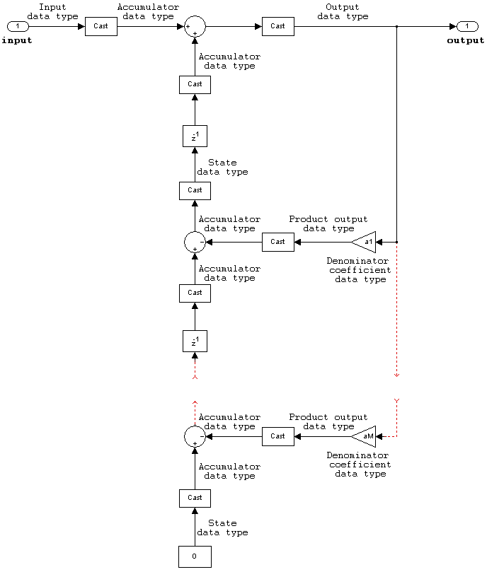
These diagrams show the filter structure and the data types used within the Allpole Filter block for fixed-point signals.
You cannot specify the state data type on the block mask for this structure because the output states have the same data types as the output.


States are complex when either the inputs or the coefficients are complex.


Extended Capabilities
C/C++ Code Generation
Generate C and C++ code using Simulink® Coder™.
Fixed-Point Conversion
Design and simulate fixed-point systems using Fixed-Point Designer™.
Version History
Introduced in R2011b
See Also
MATLAB Command
You clicked a link that corresponds to this MATLAB command:
Run the command by entering it in the MATLAB Command Window. Web browsers do not support MATLAB commands.
Select a Web Site
Choose a web site to get translated content where available and see local events and offers. Based on your location, we recommend that you select: .
You can also select a web site from the following list
How to Get Best Site Performance
Select the China site (in Chinese or English) for best site performance. Other MathWorks country sites are not optimized for visits from your location.
Americas
- América Latina (Español)
- Canada (English)
- United States (English)
Europe
- Belgium (English)
- Denmark (English)
- Deutschland (Deutsch)
- España (Español)
- Finland (English)
- France (Français)
- Ireland (English)
- Italia (Italiano)
- Luxembourg (English)
- Netherlands (English)
- Norway (English)
- Österreich (Deutsch)
- Portugal (English)
- Sweden (English)
- Switzerland
- United Kingdom (English)
