QSPI Peripheral Configuration
Map QSPI peripherals in the Infineon AURIX model to peripheral registers in the MCU
Since R2022b
Description
View and edit the map of peripherals in the Infineon® AURIX™ model to the hardware peripherals.
Using the Peripheral Configuration tool, you can:
View and edit configuration parameters for QSPI peripheral block.
Configure the global parameters. To set the group peripheral, select peripheral in Browser > Peripherals >
QSPI
. For more, see Map Tasks and Peripherals Using Hardware Mapping.Check for any conflicts between peripherals.

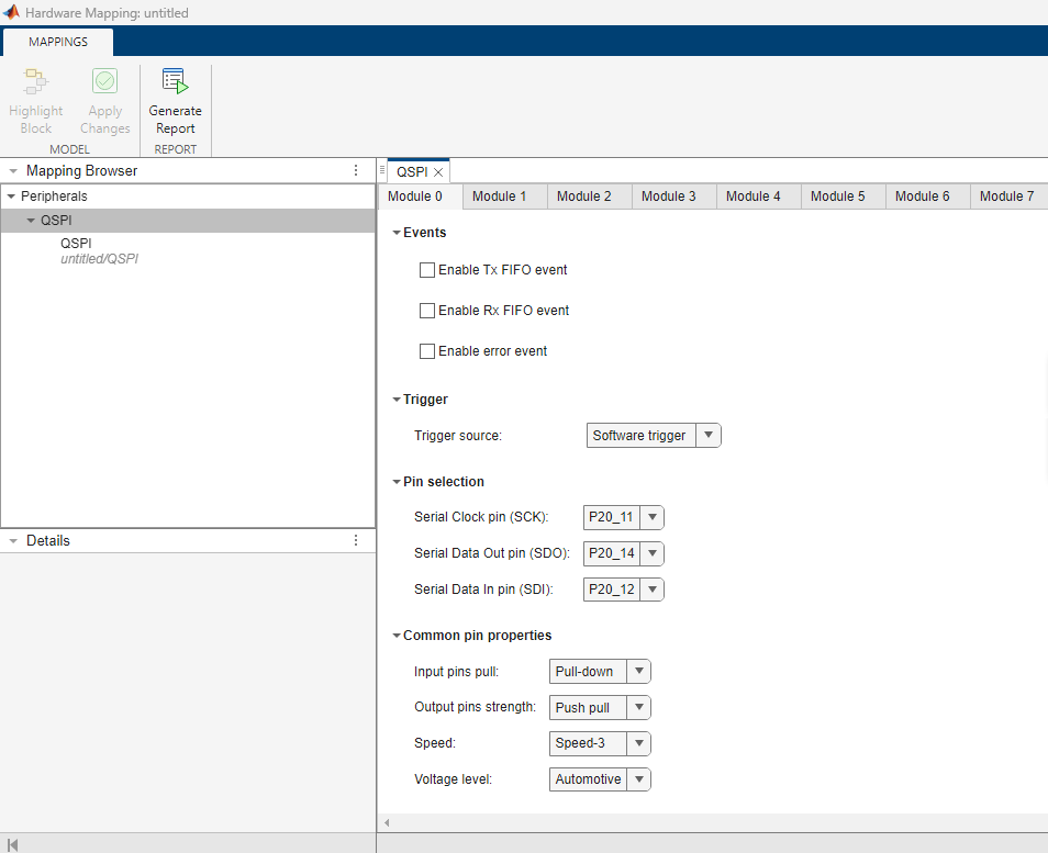
Open the QSPI Peripheral Configuration
In the Simulink toolstrip, go to Hardware tab and click Hardware Mapping.
Parameters
Global parameters
Enables the QSPI transmit FIFO event.
When you select this option, the dialog box displays the Tx FIFO Mode Selection options.
Note
Enabling this parameter, expect that the data is handled through interrupts. Therefore it is mandatory to use QSPI block (Transfer mode as SPI Transmit) during the events.
Global parameters for enable Tx FIFO event and Rx FIFO event are not applicable if the QSPI block with Transfer mode is set to
SPI transmit and receive
.
Enables the QSPI receive FIFO empty event.
When you select this option, the dialog box displays the Rx FIFO Mode Selection options.
Note
Enabling this parameter, expect that the data is handled through interrupts. Therefore it is mandatory to use QSPI block (Transfer mode as SPI Receive) during the events.
Global parameters for enable Tx FIFO event and Rx FIFO event are not applicable if the QSPI block with Transfer mode is set to
SPI transmit and receive
.
Enables the QSPI error event.
Note
Enabling this parameter, expects that the data is handled through interrupts. Therefore it is recommended to use QSPI block (SPI receive or transmit as transfer mode) during the events.
This parameter is read-only.
This read-only parameter indicates the Tx FIFO events occur based on Batch mode-1.
Dependencies
To enable this parameter, select the Enable Tx FIFO event parameter.
Enables the QSPI transmit FIFO threshold limit.
Dependencies
To enable this parameter, select the Enable Tx FIFO event parameter.
This parameter is read-only.
This read-only parameter indicates the Rx FIFO events occur based on Batch move-1.
Dependencies
To enable this parameter, select the Enable Rx FIFO event parameter.
Select the type of trigger source for the QSPI.
Select the source of hardware trigger for the QSPI.
Dependencies
To enable this parameter, set the Trigger source parameter to
Hardware trigger
.
Enables the QSPI receive FIFO threshold limit.
Dependencies
To enable this parameter, select the Enable Rx FIFO event parameter.
Select the QSPI serial clock pin selection. The list varies based on the module selected.
Select the QSPI serial data out pin selection. The list varies based on the module selected.
Select the QSPI serial data input pin selection. The list varies based on the module selected.
Channel
Select the QSPI module 0
through
7
on the hardware board.
Select the QSPI transmit mode.
Continuous
- This option activates the chip select signal till the data transfer completes.Single-transfer
- This option deactivates the chip select signal for every data element involved in the data transfer.
Specifies the rate of data communication between the peripherals connected (clock period).
Select the QSPI data heading in binary numbers.
MSB first
- the bit furthest to the left (msb) is moved first from SDO pin followed by the subsequent left bits.LSB first
- the bit furthest to the right (lsb) is moved first from SDO pin followed by the subsequent right bits.
Select the QSPI clock polarity in idle state.
Select the QSPI clock phase.
Enables the QSPI clock parity.
When you select the Enable parity option, the dialog box displays the Parity option.
Select the QSPI clock parity.
Dependencies
To enable Parity parameter, select the Enable parity parameter.
Enable to configure the QSPI block to either transmit or receive data at a time. Disable to use for both transmit and receive at a time.
Dependencies
To enable this parameter, set the Transfer mode parameter to
SPI Transmit
in the QSPI block in the Simulink® model.
Select the QSPI chip select pin.
This parameter is read-only.
Select the QSPI channel 0
through
13
. This read-only parameter indicates the channel
corresponding to the CS pin selected.
This parameter is read-only.
This parameter is read-only. Select the QSPI chip select control.
Select the QSPI chip select active level.
Introduces the selected delay between the active edge of the CS pin and the first shift clock edge.
Introduces the selected delay between shift clock period of a data block and is followed either by the deactivating edge of CS pin, or a new data block in continuous mode.
Introduces the selected delay between the end of the last TRAIL phase of a frame.
Version History
Introduced in R2022b
MATLAB Command
You clicked a link that corresponds to this MATLAB command:
Run the command by entering it in the MATLAB Command Window. Web browsers do not support MATLAB commands.
Select a Web Site
Choose a web site to get translated content where available and see local events and offers. Based on your location, we recommend that you select: .
You can also select a web site from the following list
How to Get Best Site Performance
Select the China site (in Chinese or English) for best site performance. Other MathWorks country sites are not optimized for visits from your location.
Americas
- América Latina (Español)
- Canada (English)
- United States (English)
Europe
- Belgium (English)
- Denmark (English)
- Deutschland (Deutsch)
- España (Español)
- Finland (English)
- France (Français)
- Ireland (English)
- Italia (Italiano)
- Luxembourg (English)
- Netherlands (English)
- Norway (English)
- Österreich (Deutsch)
- Portugal (English)
- Sweden (English)
- Switzerland
- United Kingdom (English)