Counterbalance Valve (IL)
High-pressure regulation valve in an isothermal liquid system

Libraries:
Simscape /
Fluids /
Isothermal Liquid /
Valves & Orifices /
Pressure Control Valves
Description
The Counterbalance Valve (IL) block represents a counterbalance pressure control valve in an isothermal liquid network. A counterbalance valve is common in applications where high-pressure events are common or when a task requires high-pressure controlled manipulation at production speeds This includes tasks such as overloading hydraulics or lowering suspended loads. The valve functions under the force balance between a spring, the back pressure at port B, and the load pressure at port L. The valve responds to changes in the pilot line pressure. When the pilot pressure exceeds the back pressure, the valve begins to open.
There is no flow between ports B and P or ports L and P.
This figure shows a typical counterbalance valve cutaway.
Valve Opening
The block balances the forces of the counterbalance valve, such that
where:
ppilot is the pressure at port P.
pload is the pressure at port L.
pback is the pressure at port B.
Fset is the accumulated force due to the spring.
kspring is the spring constant.
xspool is the linear position of the relief stage spool body. This position is relative to the unpressurized installed position.
The block sets the pressure-acting areas Apilot, Aload, and Aback according to the Pilot ratio parameter, Rpilot, such that
and the Back pressure ratio parameter, Rback, such that
A ratio of 4:1 or 3:1 is typical for counterbalance valves.
The preset force, Fspring, represents the combined spring preloading and spring force at port B. This force is a function of pset, the Set pressure differential parameter, such that
This figure shows the schematic from the Counterbalance Valve with Test Harness example where the pressure ports control the valve by acting on surfaces with differential area. The arrows show the direction of force due to pressure or spring force acting on the relief stage body. The gray sections represent a single, solid body that moves to the right when the relief stage opens. The check valve travels to the left when it opens.
Opening Parameterization
The block accepts linear or tabulated parameterizations. The check valve portion of the block operates identically to the Check Valve (IL) block.
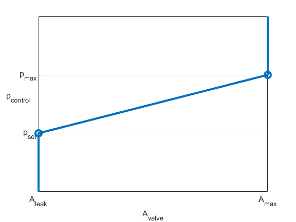
When you set Opening parameterization to
Linear - Area vs. pressure, the block calculates
the valve opening area, such that
The block calculates the normalized control pressure, , as
where pmax is the Maximum opening pressure differential parameter.
The normalized check valve pressure is
where:
pcracking is the Cracking pressure differential parameter.
pmax is the check valve Maximum opening pressure differential parameter.
When the valve is in a near-open or near-closed position in the linear parameterization, you can maintain numerical robustness in your simulation by adjusting the Smoothing factor parameter. If the Smoothing factor parameter is nonzero, the block smoothly saturates the control pressure between pcracking and pmax. For more information, see Numerical Smoothing.
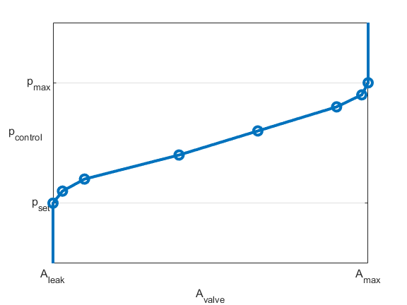
When you set Opening parameterization to Tabulated data
- Area vs. pressure, the block uses the same equations as for
the linear parameterization but with tabulated data. The tabulated data
represents area with respect to a given control pressure, where Pcontrol =
pload +
pPilotRPilot
-
pBackRBack. The first element of the Pressure differential
vector parameter is the set pressure, which is the control
pressure when the relief stage begins to open. The last element defines the
control pressure when the valve is fully open.
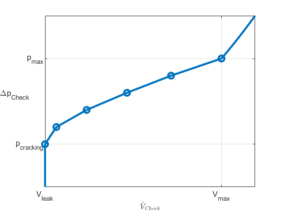
When you set Opening parameterization to Tabulated data
- Volumetric flow rate vs. pressure, the volumetric flow rate
equations refer to these quantities:
is the simulated average density of relief stage flow.
K is the flow coefficient through the relief stage.
Δpvalve is the pressure drop across the relief stage during flow.
Δpcrit is the critical pressure drop across the relief stage during flow.
pcontrol is the simulated control pressure.
pcontrol,TLU,Ref is an internally derived lookup table of changing control pressures.
pset is the set pressure differential.
Recrit is the Critical Reynolds number parameter.
Cd is the Discharge coefficient parameter.
ν is the kinematic viscosity.
KTLU,Ref is an internally derived lookup table of changing flow coefficients as a function of valve area.
is the reference volumetric flow rate vector.
ppilot,Ref, pback,Ref, pload,Ref are the pilot pressure, back pressure, and load pressure for the user-provided Reference volumetric flow rate vector parameter, respectively.
The block calculates the mass flow rate for the relief stage such that
where:
Liquid flows from the load port to the back port. The block extrapolates K to the nearest point after it calculates KTLU,Ref as
where Δpvalve,TLU,ref = pload,Ref - pback,Ref. The block calculates the control pressure as
and the reference control vector as
where:
The block internally derives Δpflow,Ref, which is the pressure drop for fluid flow in the specified reference curve. The block calculates poffset internally as
The table shows how the block controls the relief and check stages opening areas depending the Opening area parameter setting.
| Opening parameterization | Relief stage | Check stage |
|---|---|---|
Linear - Area vs.
pressure |
|
|
Tabulated - Area vs.
pressure |
|
|
Tabulated - Volumetric flow rate vs.
pressure |
|
|


Examples

Counterbalance Valve with Test Harness
Model, parameterize, and test a counterbalance valve in detailed fidelity and system level fidelity using a variant subsystem. Running the model generates a plot of the flow from the load port to the back port due to the relief action of the counterbalance valve using the detailed fidelity variant. A counterbalance valve allows an upstream flow from the back port to the load port through the check valve stage, and it allows a downstream flow from the load port to the back port through the relief stage. Counterbalance valves help with load holding, load actuation speed control, and safety.

Hydraulic Actuator with Dual Counterbalance Valves
An actuator controlled by a 4-way directional valve and loaded with an overriding load, requiring the use of counterbalance valves to prevent the load from creeping when the directional valve is in the neutral position. In the neutral position, the directional valve connects ports A and B to the reservoir while blocking the pressure port P. The counterbalance valves block flow from returning to the reservoir, thus holding the actuator in place.
Assumptions and Limitations
The block operates in only the internal drain–external pilot, non-vented configuration.
When you set Opening parameterization to
Tabulated data
						- Volumetric flow rate vs. pressure
, the block uses values of volumetric flow rate with respect to the pressure drop across the relief stage to generate reference curves. The block assumes that the pilot port and back port are open to atmospheric pressure.