Poppet Valve (IL)
Poppet valve in an isothermal liquid network

Libraries:
Simscape /
Fluids /
Isothermal Liquid /
Valves & Orifices /
Flow Control Valves
Description
The Poppet Valve (IL) block represents a flow-control valve in an isothermal liquid system. The poppet can either be a cylinder or a ball. You can choose between sharp-edged and conical seats. The poppet opens or closes according to the displacement signal at port S. A positive signal retracts the poppet and opens the valve.
Poppet Valve Schematic
Poppet Valve Top View
Cylindrical Stem Poppet Opening Area
The opening area of the valve is calculated as:
where:
h is the vertical distance between the outer edge of the cylinder and the seat, indicated in the schematic above.
θ is the Seat cone angle.
ds is the Stem diameter.
Aleak is the Leakage area.
The opening area is bounded by the maximum displacement hmax:
For any stem displacement larger than hmax, Aopen is the sum of the maximum orifice area and the Leakage area:
For any combination of the signal at port S and the cylinder offset less than 0, the minimum valve area is the Leakage area.
Round Ball Poppet Opening Area
The opening area of the valve is calculated as:
where:
h is the vertical distance between the outer edge of the cylinder and the seat, indicated in the schematic above.
rO is the seat orifice radius, calculated from the Seat orifice diameter.
rB is the radius of the ball, calculated from the Ball diameter.
Gsharp is the geometric parameter:
Aleak is the Leakage area.
The opening area is bounded by the maximum displacement hmax:
For any ball displacement larger than hmax, Aopen is the sum of the maximum orifice area and the Leakage area:
For any combination of the signal at port S and the ball offset that is less than 0, the minimum valve area is the Leakage area.
The opening area of the valve is calculated as:
where:
h is the vertical distance between the outer edge of the cylinder and the seat, indicated in the schematic above.
θ is the Seat cone angle.
Gconical is the geometric parameter: where rB is the ball radius.
Aleak is the Leakage area.
The opening area is bounded by the maximum displacement hmax:
For any ball displacement larger than hmax, Aopen is the sum of the maximum orifice area and the Leakage area:
For any combination of the signal at port S and the ball offset that is less than 0, the minimum valve area is the Leakage area.
Numerically Smoothed Displacement
The block calculates the poppet displacement, h, such that
where:
S is the physical signal input.
Smin is the Poppet position when in the seat parameter.
hMax is the maximum displacement.
If the Smoothing factor parameter is nonzero, the block smoothly
saturates the poppet displacement between 0 and
hMax.
For more information, see Numerical Smoothing.
Mass Flow Rate Equation
Mass is conserved through the valve:
The mass flow rate through the valve is calculated as:
where:
Cd is the Discharge coefficient.
Avalve is the current valve open area.
Aport is the Cross-sectional area at ports A and B.
is the average fluid density.
Δp is the valve pressure difference pA – pB.
The critical pressure difference, Δpcrit, is the pressure differential associated with the Critical Reynolds number, Recrit, the flow regime transition point between laminar and turbulent flow:
Pressure loss describes the reduction of pressure in the valve due to a decrease in area. PRloss is calculated as:
Pressure recovery describes the positive pressure change in the valve due to an increase in area. If you do not want to capture this increase in pressure, clear the Pressure recovery check box. In this case, PRloss is 1.
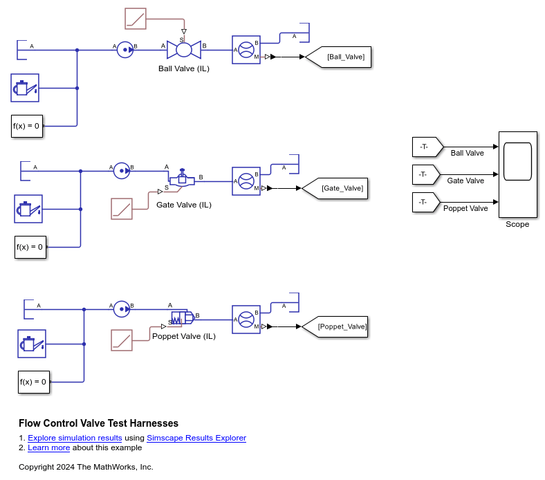
Examples
This example uses test harnesses to compare the Ball Valve (IL), Gate Valve (IL), and Poppet Valve (IL) blocks. A test harness is a minimum viable model that you can use to parameterize blocks or isolate dynamics.
Model
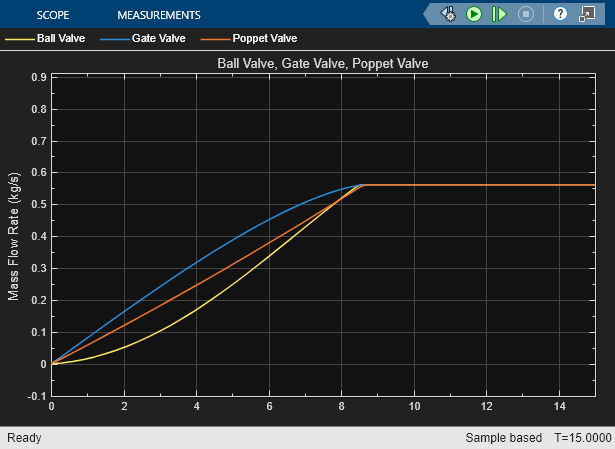
Simulation Results from Scopes
This figure shows the mass flow rate through each of the valves. All three valves start closed and slowly open before reaching their maximum area. At the maximum area, the mass flow rate also reaches its maximum and cannot increase further. Each curve has a different profile while opening because each valve has a different area profile that depends on the valve geometry.
Extended Examples

Hydraulic Motor Driven by Load-Sensing Pump
A circuit that is equipped with a load-sensing velocity regulator installed between the pump and directional valve. Unlike a conventional meter-in velocity control, the load-sensing device automatically adjusts output pressure of the pump in such a way that it equals the sum of the preset pressure drop across the pressure-compensated flow control valve and the pressure induced by load. The pilot-operated pressure-relief valve in the Load-Sensing Velocity Control block is built of the Poppet Valve (IL) and the Pilot Valve Actuator (IL) blocks.
Ports
Conserving
Input
Parameters
Extended Capabilities
Version History
Introduced in R2020a
See Also
Poppet Valve (G) | Poppet Valve (TL) | Needle Valve (IL) | Gate Valve (IL)