Hydraulic Actuator with Counterbalance Valve
The model demonstrates extension, retraction, and holding of a hydraulic actuator with a counterbalance valve. An open-center 4-way directional valve controls a double-acting actuator, and a constant flow rate source equipped with a pressure relief valve serves as the power unit. The actuator is subject to an external force that tries to extend the actuator. The counterbalance valve modulates the return flow into port L, preventing the loss of control of the actuator in extending, as well as holding the piston in place at the neutral position of the valve. Port A of the actuator connects to port P of the counterbalance valve, making it impossible for the cylinder to move until the pressure at port A builds up to a certain level.
To keep the position of the actuator at the neutral position of the 4-way valve, the counterbalance valve has the set pressure differential of  , where 2 is the safety factor,
  is the load,
  is the piston area in chamber B of the cylinder. The actuator begins to extend when the pilot pressure increases so that
  , where
  is the load pressure,
  and
and  are the pilot pressure and pilot ratio, and
  and
and  are the back pressure and back pressure ratio, respectively.
Model

Simulation Results from Scopes

Simulation Results from Simscape Logging
The plots below show the pressures in the cylinder with the positions of the spool and piston.

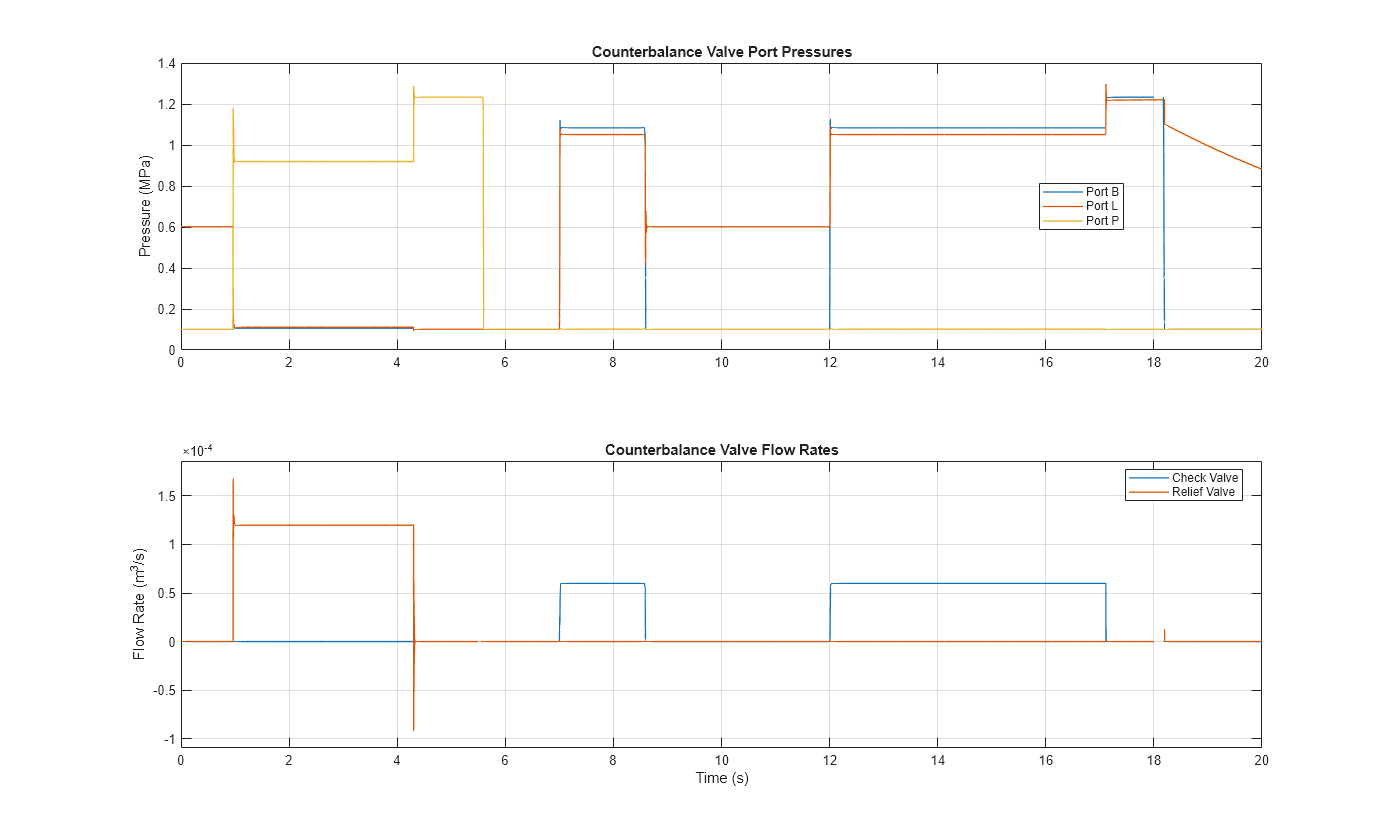
The plots below show the port pressures and flow rates of the counterbalance valve.