Main Content

modulator

R2026b

Modulator object

Description

Use the modulator object to create a modulator element. A modulator is a 2-port RF circuit object. You can use this element in the rfbudget object and the circuit object.

Creation

Description

mod = modulator creates a modulator object, mod, with default property values.

example

mod = modulator(Name=Value) creates a modulator object with additional properties specified by one or more name-value arguments. Properties not specified retain their default values.

example

Properties

expand all

Name of modulator, specified as the comma-separated pair consisting of 'Name' and a character vector. All names must be valid MATLAB® variable names.

Example: Name='mod'

Modulator model, specified as one of the following:

  • 'poly' — Cubic polynomial model. (since R2026b)

  • 'rfsys' — RF system data model. This value is automatically set when you create a modulator object using system data from a CSV file or using the rfSystemParameters object, rfPartSelector object, or RF Part Catalog app. (since R2026b)

Since R2026b

Modulator converter type, specified as one of the following:

  • 'Up' — Up converter

  • 'Down' — Down converter

Example: ConverterType='Down'

Since R2026a

Sideband of a modulator, specified as either:

  • 'upper' — RF carrier frequency is higher than local oscillator frequency.

  • 'lower' — RF carrier frequency is lower than local oscillator frequency.

This table summarizes the modulator operations when Sideband is set.

Input/OutputConverterTypeSidebandOperation
RF/IF'Down''lower'IF = LO - RF
'upper'IF = RF - LO
IF/RF'Up''lower'RF = LO - IF
'upper'RF = LO + IF

Example: Sideband='upper'

Available power gain, specified as a nonnegative scalar in dB.

Example: Gain=10

Noise figure, specified as a real finite nonnegative scalar in dB.

Example: NF=10

Since R2026a

Second-order input-referred intercept point, specified as a real positive number in dBm.

Example: IIP2=8

Since R2026a

Third-order input-referred intercept point, specified as a real positive number in dBm.

Example: IIP3=10

Since R2026a

Input 1 dB compression point, specified as a real positive number in dBm.

Example: IP1dB=20

Since R2026a

Input saturation point, specified as a positive real number in dBm.

Example: IPsat=20

Local oscillator frequency, specified as a real finite positive scalar in Hz.

Example: LO=2e9

Name of the two-port Touchstone file that contains modulator data, specified as a string scalar or character vector.

Example: FileName='default.s2p'

Since R2026a

Modulator system data, specified as an rfSystemParameters object.

Example: SystemData=rfSystemParameters('Mod_model.csv')

Ideal image reject filtering at the input of the modulator, specified as a numeric or logical 1 (true) or 0 (false). Setting this property to false or 0 might affect harmonic balance results.

Example: ImageReject=1

Example: ImageReject=true

Ideal channel select filtering at the output of the modulator, specified as a numeric or logical 1 (true) or 0 (false). Setting this property to false or 0 might affect harmonic balance results.

Example: ChannelSelect=1

Example: ChannelSelect=false

Input impedance, specified as a positive real part finite scalar in ohms. You can also use a complex value with a positive real part.

Example: Zin=40

Output impedance, specified as a scalar in ohms. You can also use a complex value with a positive real part.

Example: Zout=40

Number of ports, specified as a scalar integer. This property is read-only.

Names of port terminals, specified as a cell vector. This property is read-only.

Object Functions

cloneCreate copy of existing circuit element or circuit object

Examples

collapse all

Create a downconverter modulator with a local oscillator (LO) frequency of 100 MHz.

m = modulator(ConverterType='Down',LO=100e6)
m = 
  modulator: Modulator element

             Name: 'Modulator'
    ConverterType: 'Down'
               LO: 100000000
             Gain: 0
              Zin: 50
             Zout: 50
               NF: 0
             IIP2: Inf
             IIP3: Inf
            IP1dB: Inf
            IPsat: Inf
            OPsat: Inf
      ImageReject: 1
    ChannelSelect: 1

Create a modulator object with a gain of 4 dB and local oscillator (LO) frequency of 2 GHz. Create another modulator object has an output third-order intercept (OIP3) of 13 dBm.

mod1 = modulator(Gain=4,LO=2e9);
mod2 = modulator(OIP3=13);

Build a two-port circuit using the modulators.

c = circuit([mod1 mod2])
c = 
  circuit: Circuit element

    ElementNames: {'Modulator'  'Modulator_1'}
        Elements: [1×2 modulator]
           Nodes: [0 1 2 3]
            Name: 'unnamed'

Create an amplifier with a gain of 4 dB.

a = amplifier(Gain=4);

Create a modulator with an IIP3 of 13 dBm.

m = modulator(IIP3=13);

Create an N-port element using passive.s2p.

n = nport('passive.s2p');

Create an RF element with a gain of 10 dB.

r = rfelement(Gain=10);

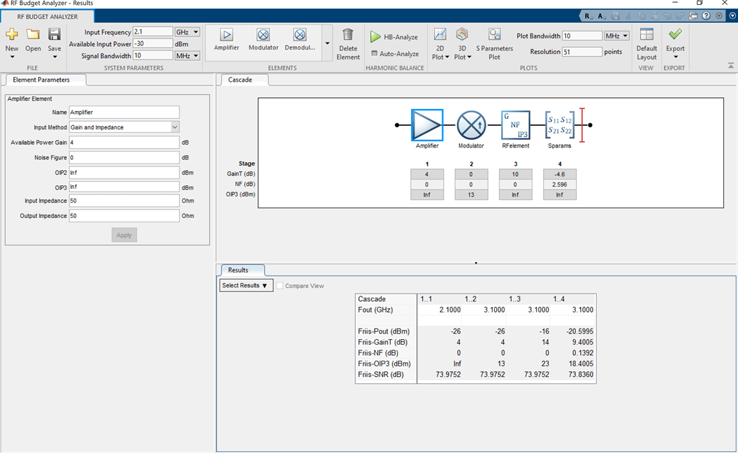
Calculate the RF budget of a series of RF elements at an input frequency of 2.1 GHz, an available input power of –30 dBm, and a bandwidth of 10 MHz.

b = rfbudget([a m r n],2.1e9,-30,10e6)
b = 
  rfbudget with properties:

               Elements: [1x4 rf.internal.rfbudget.Element]
         InputFrequency: 2.1 GHz
    AvailableInputPower: -30 dBm
        SignalBandwidth:  10 MHz
                 Solver: Friis      
             AutoUpdate: true

   Analysis Results
        OutputFrequency: (GHz) [  2.1    3.1    3.1     3.1]
            OutputPower: (dBm) [  -26    -26    -16   -20.6]
         TransducerGain: (dB)  [    4      4     14     9.4]
                     NF: (dB)  [    0      0      0  0.1391]
                   IIP3: (dBm) [  Inf      9      9       9]
                   OIP3: (dBm) [  Inf     13     23    18.4]
                    SNR: (dB)  [73.98  73.98  73.98   73.84]

Type the show command at the command window to display the analysis in the RF Budget Analyzer app.

show(b)
amp_rf_app.png

Version History

Introduced in R2017a

expand all