Control Cartesian Position of KINOVA Gen3 Robot End-Effector Using Inverse Kinematics Block and KINOVA KORTEX System Object
This example shows how to solve inverse kinematics problems using Rigid Body Trees and how to control the KINOVA Gen3 7-DoF Ultralightweight Robot Arm to follow the desired trajectory.
Introduction
Robotics System Toolbox™ Support Package for KINOVA® Gen3 Manipulators enables you to control manipulators using MATLAB® and Simulink®. This support package utilizes APIs provided by robot manufactures to acquire various sensor data, simulate robot models, and to control the robot. Prototype algorithms and perform simulations of these robots using rigid body tree models from Robotics System Toolbox or Simscape™ Multibody™ robot models. Connect with the robot hardware to test and validate your algorithms.
In this example, the InverseKinematics System object™ from Robotics System Toolbox is used to calculate the actuator joint angles for the specified Cartesian pose. The InverseKinematics System object creates an inverse kinematic (IK) solver to calculate the joint configurations for a desired end-effector pose based on a specified rigid body tree model.
Prerequisites
If you are new to Simulink, watch the Simulink Quick Start.
Perform the initial of the support package using Hardware Setup screens.
Refer to Connect to Kinova Gen3 Robot and Manipulate the Arm Using MATLAB for information on the communication interface between MATLAB and the robot.
Refer to Control KINOVA Gen3 Robotic Manipulator Using KINOVA KORTEX System Object and Simulink for more information on the KORTEX™ system object from KINOVA Robotics.
Model
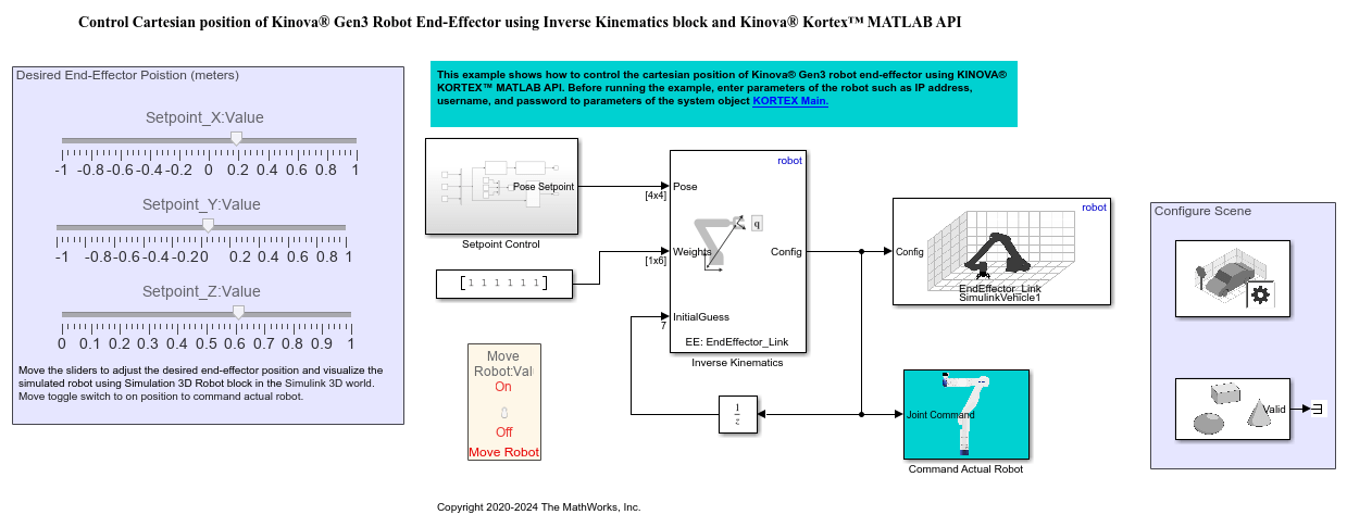
Open the manipdemo_ikgen3 model.
Inverse Kinematics
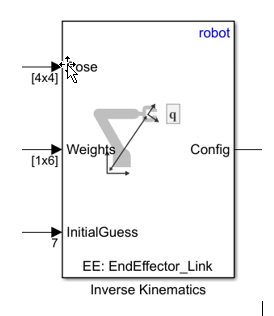
The inverseKinematics System object creates an inverse kinematic (IK) solver to calculate joint configurations for a desired end-effector pose based on a specified rigid body tree model. Create a rigid body tree model for your robot using the rigidBodyTree class. This model defines all the joint constraints that the solver enforces. If a solution is possible, the joint limits specified in the robot model are obeyed.
Setpoint Control
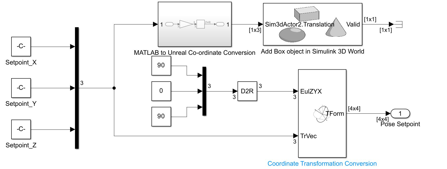
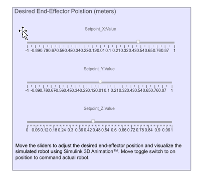
The Setpoint Control subsystem takes the desired Cartesian position and pose of the end-effector of the robot and applies a coordinate transformation to generate the desired for the Inverse Kinematics block. In this example, the desired orientation of the end-effector is fixed, and the Cartesian position is controlled via three input sliders. The subsystem also contains the Simulation 3D Actor block from Simulink 3D Animation™ to locate object in Simulink 3D world.
Input Sliders
Robot Visualization and Command Actual Robot
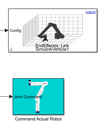
Simulation 3D Robot block from Robotics System Toolbox™ enables visualization of RigidBodyTree objects in Simulink 3D world. The command actual robot subsystem uses Kortex system object from KINOVA Robotics to connect and control the Gen3 robot.
Run the Model
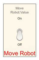
Note: The robot will move according to the specified input, so please have the E-STOP close to you. Ensure that 'Move Robot' toggle switch is in off position before running the model. This will prevent the sudden and unintended motion of the robot.
After configuring the robot specific parameter in the Kortex system object properties, navigate to the SIMULATE tab and press Run. The simulated robot will move to the position specified by the slider position, and any change in the slider position will be reflected in the end-effector position of the simulated robot.

After validating the joint configuration generated by the inverse kinematic block, change 'Move Robot' toggle switch to on position. This will send the joint angles generated by the inverse kinematic block to the robot.
Run the Model without Simulink 3D Animation
In the absence of Simulink 3D Robot and Actor block, this model can still be used to control the Gen3 robot. Comment out the Simulink 3D Robot block and Simulink 3D Actor in 'Setpoint Control' subsystem before running the model without valid installation of Simulink 3D Animation. However, validate the joint configuration generated by the inverse kinematic block using display or scope blocks before sending it to the actual robot.