Read Current Joint Angle of KINOVA Gen3 and Publish to ROS Network
This example shows how to deploy robotics algorithms developed in Simulink as a standalone ROS node to NVIDIA Jetson compute boards. The example includes ROS Subscribe block to get feedback from the robot and relay the same information over a new ROS topic using ROS Publish block.
Required Products
MATLAB®
Simulink®
Robotics System Toolbox™
ROS Toolbox
Simulink Coder
Required Hardware
KINOVA® Gen3 Robot
NVIDIA Jetson Nano OR TX2 OR Xavier
Introduction
Robotics System Toolbox Support Package for Manipulators enables you to control manipulators using MATLAB and Simulink. The support package utilizes ROS packages provided by robot manufactures to acquire various sensor data, simulate robot models, and control the robot.
You can further utilize the standalone ROS node generation feature from the ROS Toolbox to convert robotics algorithms into a standalone ROS node. Such a node can be automatically deployed to various compute boards using Simulink. The deployment of robotics algorithms eliminates the requirement of constant communication between host PC (with MATLAB installed) and the robot. This is beneficial in many application workflows. For more information on the deployment workflow refer to Object Detection and Motion Planning Application with Onboard Deployment.
In this example, sensor_msgs/JointState ROS message is used to get current joint configuration of Kinova Gen3 robot. One of the joint angles is then extracted form the received data and published via a new ROS topic with std_msgs/Float32 message.
Prerequisites
If you are new to Simulink, watch the Simulink Quick Start.
Perform the Setup and Configuration of the Jetson compute board as per instructions mentioned in Configure NVIDIA Jetson Board for Object Detection and Motion Planning.
Refer Read Current Joint Angles from KINOVA Gen3 Robot Arm to know more about the ROS interface between for Kinova Gen3 robot.
Connect to KINOVA Gen3 Robot and Initiate Required ROS Nodes to Control the Robot
Open the terminal from the catkin workspace containing ros_kortex ROS packages in the Jetson board. Execute 'source devel/setup.bash' and the following command in the terminal to launch required ROS nodes.
roslaunch kortex_driver kortex_driver.launch ip_address:=192.168.0.106 gripper:=robotiq_2f_85 start_rviz:=false start_moveit:=false
Also, replace the IP address of the robot and gripper based on the actual hardware setup. For more information on the roslaunch command, see GitHub page of KINOVA Robotics.
If the hardware setup and the IP address are correct, a message 'The Kortex driver has been initialized correctly!' displays on the terminal window.
Connect to the ROS Master Running on Jetson Board from MATLAB
Configure ROS network parameter for connectivity and deployment as per setup instructions mentioned under the section Configure the Connection to the ROS Device in Generate a Standalone ROS Node from Simulink.
Note: The workspace folder must be the same in which you have downloaded the ROS packages from Kinova Robotics.
Because you already started the ROS core in the earlier step, you need not start the ROS core on the rosdevice using runCore command from MATLAB.
Model
Open the manipdemo_relayJointAnglesROS model.

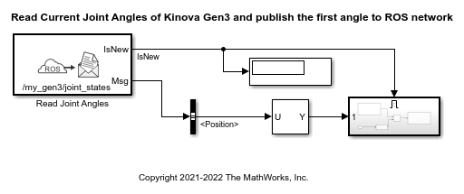
The model consists of a ROS Subscribe block, which is configured for /my_gen3/joint_states ROS topic. As explained in the Github page of Kinova Robotics, the first part of the ROS topic, my_gen3, might be different based on the robot name that is set during the roslaunch command. The joint angles position is extracted from the received message and then the value of the first joint angle is passed to the subsystem block.

The subsystem creates a std_msgs/Float32 type blank message and populate the data with first joint angle. The populated message is then published using /relay_joint_states topic.
Run and Verify the Model Using MATLAB Connectivity
In the previous step, the required ROS nodes are already launched from the Jeston board, to ensure the connection with the robot and compute board. Open Simulation on the Simulink toolbar and then click Run. This establishes a connection between MATLAB and ROS master running on the Jetson board.
To verify the intended behavior of the Simulink model, type rostopic list in the MATLAB command window. The ROS topic /relay_joint_states should be listed in the output.
Echo /relay_joint_states by executing the rostopic echo /relay_joint_states command . This prints stream of float values in the MATLAB command window. Move the Joint 1 of the robot using Joystick or Kinova webapp, and verify that the value changes. Once verified, stop the simulation.
Run and Verify the Model using Standalone ROS deployment
Navigate to ROS tab and press Build & Deploy. This will generate the code from the model, transfer it to specified workspace on Jetson and build it.
You can use isNodeRunning, runNode and stopNode feature of rosdevice to interact with the deployed ROS node. Repeat the same verification steps as mentioned in the earlier section to verify the intended behavior of the autogenerated ROS node.