Connect to ROS-Enabled Robot from Simulink over ROS 2
This example shows you how to configure a Simulink® model to send and receive information from a ROS-based simulator such as Gazebo® over a ROS 2 network.
Introduction
You can use Simulink to connect to a ROS-enabled physical robot or to a ROS-enabled robot simulator such as Gazebo. This example shows how to:
Configure Simulink to connect to a ROS-enabled robot simulator using ROS 2.
Send velocity commands to a simulated robot.
Receive position information from a simulated robot.
Prerequisites
To run this example, you are require to set up Docker in your host environment (Windows Subsystem for Linux (WSL), Linux or Mac) and create a Docker image for Gazebo. For more information on how to configure Docker, see Install and Set Up Docker for ROS, ROS 2, and Gazebo.
Start Docker Container
With the prerequisites set up and the Docker image created, the first step is to launch an instance of Docker container.
To start a Docker container, run the following command in WSL/Linux/Mac terminal:
$ docker run -it --net=host -v /dev/shm:/dev/shm --name ros2_diff_drive <image-name>
Here, 'ros2_diff_drive' is the name of the Docker container. Replace the <image-name> with the name of the Docker image created in the prerequisite section.
Start Gazebo Robot Simulator
Once the container is running, start the Gazebo robot simulator inside the Docker container.
Open a terminal within the Docker container by executing the following command in the WSL/Linux/Mac terminal:
$ docker exec -it ros2_diff_drive /bin/bash
Here, 'ros2_diff_drive' is the docker container name.
In the Docker container terminal, launch the TurtleBot in a Gazebo world by running the following command:
$ source start-gazebo-empty-world.sh
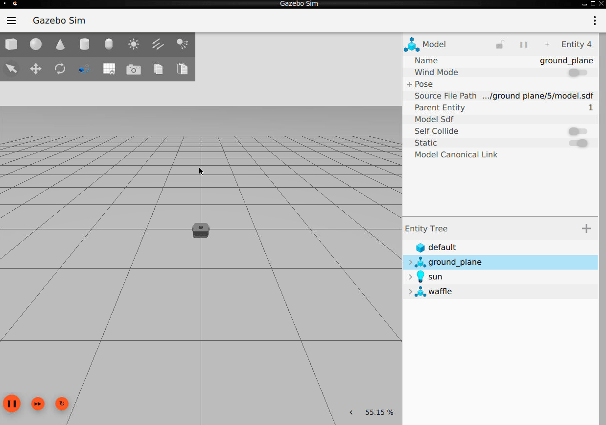
To view the Gazebo world, open a web browser on your host machine and connect to the URL <docker-ip-address>:8080. If Docker is running on your host machine, you can simply use localhost:8080. You can now visualize and interact with the Gazebo world directly in your web browser.
Configure MATLAB for ROS 2 Network
Launch MATLAB on your host machine and set the ROS_DOMAIN_ID environment variable to 25 and configure the ROS Middleware in MATLAB to rmw_fastrtps_cpp to match the robot simulator's ROS settings. For detailed steps, refer to Switching Between ROS Middleware Implementations.
Once the domain ID is set, run the following command in MATLAB to verify that the topics from the robot simulator are visible:
setenv('ROS_DOMAIN_ID','25')
ros2 topic list
/camera/camera_info
/camera/image_raw
/camera/image_raw/compressed
/camera/image_raw/compressedDepth
/camera/image_raw/theora
/camera/image_raw/zstd
/clock
/cmd_vel
/imu
/joint_states
/odom
/parameter_events
/robot_description
/rosout
/scan
/tf
/tf_static
The simulator receives and sends messages on the following topics:
Receives
geometry_msgs/Twistvelocity command messages on the /cmd_vel topic.Sends
nav_msgs/Odometrymessages to the/odomtopic.
Open Existing Model
After connecting to the ROS 2 network, open the example model.
open_system('robotROS2ConnectToRobotExample');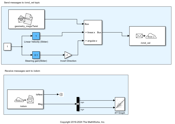
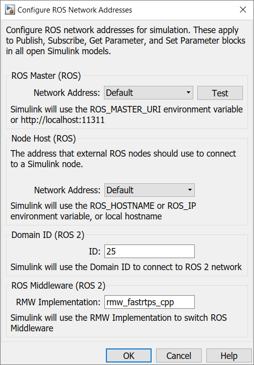
Configure Simulink to Connect to ROS 2 Network
Setup the Simulink ROS preferences to communicate with the robot simulator.
From the Simulation tab Prepare gallery, click ROS Network under ROS TOOLBOX.
In the Configure ROS Network Addresses dialog, under Domain ID (ROS 2), set ID to
25. This ID value matches the domain ID of the ROS 2 network on the docker container, where the messages from Gazebo in ROS network are received.
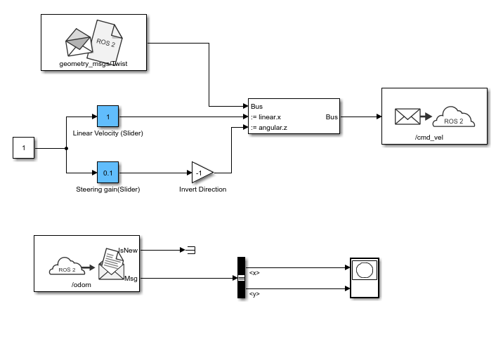
Send Velocity Commands To Robot
Create a publisher that sends control commands (linear and angular velocities) to the simulator. Make these velocities adjustable by using Slider Gain blocks.
ROS uses a right-handed coordinate system, so X-axis is forward, Y-axis is left and Z-axis is up. Control commands are sent using a geometry_msgs/Twist message, where linear.x indicates linear forward velocity (in meters/sec), and angular.z indicates angular velocity around the Z-axis (in radians/sec).
Open a new Simulink model.
On the ROS tab, under CONNECT, click Select a ROS Network and select Robot Operating System 2 (ROS 2).
From the ROS Toolbox > ROS 2 tab in the Library Browser, drag a Publish block to the model. Double-click the block.
Set Topic source to
Specify your own. Enter/cmd_velin the Topic field. Click Select next to Message Type, selectgeometry_msgs/Twistfrom drop down list, and click OK.From the ROS Toolbox > ROS 2 tab in the Library Browser, drop a Blank Message block to the model. Double-click the block.
Click Select next to Message type and select
geometry_msgs/Twist.Set Sample time to
0.01and click OK.From the Simulink > Signal Routing tab in the Library Browser, drag a Bus Assignment block to the model.
Connect the output of the Blank Message block to the
Businput of the Bus Assignment block, and the Bus output to the input of the Publish block.Double-click the Bus Assignment block.
In the list of elements in the bus, expand both
linearandangular. Selectlinear>xandangular>z. Then, click Select. If these elements are not listed as elements of the input bus, close the dialog box. To ensure that the bus information is propagated, on the Modeling tab, click Update Model. Then, reopen the dialog box.In the list of elements that are being assigned, select
???signal1. Then, click Remove.Click OK to close the dialog box.
Add a Constant block, a Gain block, and two Slider Gain blocks. Connect them together as shown in picture below, and set the Gain value to
-1.
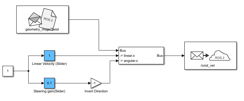
Set the limits, and current parameters of the linear velocity slider to
0.0to2.0, and1.0respectively. Set the corresponding parameters of the steering gain slider to-1.0to1.0, and0.1.
Receive Location Information From Robot
Create a subscriber to receive messages sent to the /odom topic. You will also extract the location of the robot and plot its path in the XY-plane.
From the ROS Toolbox > ROS 2 tab in the Library Browser, drag a Subscribe block to the model. Double-click the block.
Set Topic source to
Select From ROS network, and click Select next to the Topic box. Select "/odom" for the topic and click OK. Note that the message typenav_msgs/Odometryis set automatically.From the Simulink > Signal Routing tab in the Library Browser, drag a Bus Selector block to the model.
Connect the Msg output port of the Subscribe block to the input port of the Bus Selector block.
Double-click the Bus Selector block.
In the list of elements in the bus, expand
pose>pose>positionand selectxandy. To add these elements to the block output, click . If these elements are not listed as elements of the input bus, close the dialog box. To ensure that the bus information is propagated, on the Modeling tab, click Update Model. Then, reopen the dialog box.
In the list of output elements, select
signal1andsignal2. To remove these elements, click .
.From the Simulink > Sinks tab in the Library Browser, drag an XY Graph block to the model. Connect the
XandYoutput ports of the Bus Selector block to the input ports of the XY Graph block.
The following figure shows the complete model. A pre-configured model is included for your convenience.
Configure and Run Model
From the Modeling tab, click Model Settings. In the Solver pane, set Type to
Fixed-stepand Fixed-step size to0.01.Set simulation Stop time to
inf.Click Run to start the simulation.
In both the simulator and XY plot, you should see the robot moving in a circle.
While the simulation is running, change the values of Slider Gain blocks to control the robot. Double-click the XY Graph block and change the
XandYaxis limits if needed (you can do this while the simulation is running).To stop the simulation, click Stop.
Clean up Docker container
To delete Docker container, run the following command in WSL/Linux/Mac terminal:
$ docker rm ros2_diff_drive
Here, 'ros2_diff_drive' is the name of Docker container.