Measure IIP3 of Device Under Test
R2026bUse the IIP3 Testbench block to measure the input third-order intercept (IIP3) of device under test (DUT).
Connect the blocks as shown in the model.
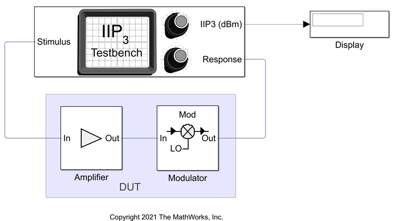
Set the parameters for DUT and the testbench.
Amplifier block:
Available power gain —
10dBIntercept points convention —
InputIP3 —
32dBm
Mixer block:
Available power gain —
5dBLocal oscillator frequency —
2.0GHzAdd Image Reject filter —
onIntercept points convention —
InputIP3 —
35dBmFilter type —
HighpassImplementation —
Constant per carrierPassband edge frequency —
2.0GHz
IIP3 Testbench block:
Input frequency (Hz) —
2.1e9Output frequency (Hz) —
0.1e9Simulate noise (both stimulus and DUT internal) —
off
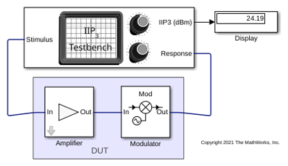
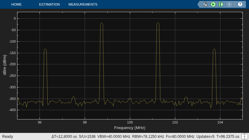
Run the model. You will see that the display shows an IIP3 value of 24.19 dBm. This value can be verified analytically using the equation provided in [1].
IIP3 of the DUT = – 10*log10(1/10^((32)/10) + 10^(10/10)/10^((35)/10)) = 24.2099 dBm
where,
IIP3 of the amplifier in linear scale = 10^((32)/10)
IIP3 of the mixer in linear scale = 10^((35)/10)
Available power gain of the amplifier = 10^(10/10)
References
[1] Razavi, Behzad. “Basic Concepts “ in RF Microelectronics, 2nd edition, Prentice Hall, 2012.
See Also
OIP2 Testbench | OIP3 Testbench | IIP3 Testbench | IIP2 Testbench

