IMU-Based Motor Speed Control on Arduino Using SERCOM Serial Interrupts
This example shows how to implement a real-time closed-loop motor control system using the on-board IMU sensor of the Arduino Nano 33 IoT. The Arduino uses SERCOM serial interrupts for communication with a host computer.
Using SERCOM serial ports instead of default serial port enables dedicated, interrupt-driven communication between Arduino hardware and the host computer. Use SERCOM serial ports on your Arduino hardware to facilitate reliable, real-time data exchange between them.
In this example, the host computer processes accelerometer data received from the Arduino and computes the appropriate motor speed and direction. The host computer then sends these control signals back to the Arduino hardware. Using SERCOM serial interrupts, the Arduino immediately updates the motor speed and direction based on the received commands.
The diagram illustrates in more detail the communication between the host computer, the Arduino board, and the motor.

1. The Arduino reads IMU sensor data and sends this data to the host computer using a SERCOM-configured serial port (Sercom 0).
2. The host computer calculates the left and right motor speeds and sends these speeds back to the Arduino using the SERCOM serial port. The SERCOM port uses interrupts for immediate data handling.
3. The Arduino processes the received speeds inside an interrupt service routine (ISR) and quickly updates the motor.
Supported Arduino Boards
Arduino MKR 1000
Arduino MKR ZERO
Arduino MKR Wi-Fi® 1010
Arduino Nano 33 IoT
Required Hardware
SERCOM interrupt supported Arduino board. This example uses Arduino Nano 33 IoT hardware board.
DC motor and motor driver (Nano motor carrier) or server motors as output peripherals.
Future Technology Devices International (FTDI) to send data to host and read data from host.
Jumpers and wires to make connections between Arduino, motor driver, and motors.
Hardware Setup
For instructions to install a USB to serial FTDI driver, see Install USB to Serial Device Driver and Connect Arduino and USB to Serial Adaptor sections in the Send and Receive Data Between Arduino and Host Using Serial Communication example.
Deploy Target Model
Open the arduinoTargetSERCOMInterrupt Simulink model.
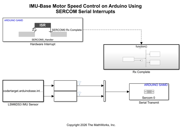
This model runs on the Arduino Nano 33 IoT hardware and performs the following functions.
Acquire IMU data — The LSM6DS3 IMU Sensor block continuously acquires accelerometer and gyroscope data from the onboard IMU sensor on the Arduino hardware.
Transmit data to Host — The Serial Transmit block sends the IMU data to the host computer over the SERCOM 0 port.
Handle interrupts for serial communication — The Hardware Interrupt block is configured to trigger on the SERCOM0 Rx complete event to respond immediately to the incoming serial data.
Receive commands from host — Within the Rx Complete enabled subsystem, the Serial Receive block captures the motor speed and direction sent from the host computer.
The following diagram shows the Rx Complete enabled subsystem.
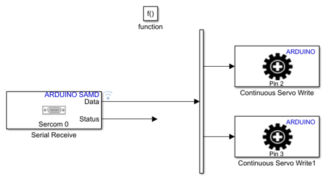
Update motor — The model receives the commands from the host computer to update the motor in real time using the Continuous Servo Write blocks for the left and right motors.
To prepare for deploying this model on the Arduino hardware, configure the Sercom properties in the Configuration Parameters dialog box of the model. In the Configuration Parameters dialog box, Enable SERCOM as Serial and configure the Sercom baud rate and Sercom configuration parameters.
To deploy the model on your Arduino hardware, on the Hardware tab of the model, in the Mode section, select Run on board and then click Build, Deploy & Start.
Configure Host Model
Open the arduinoHostSerialSetMotorSpeed Simulink model.
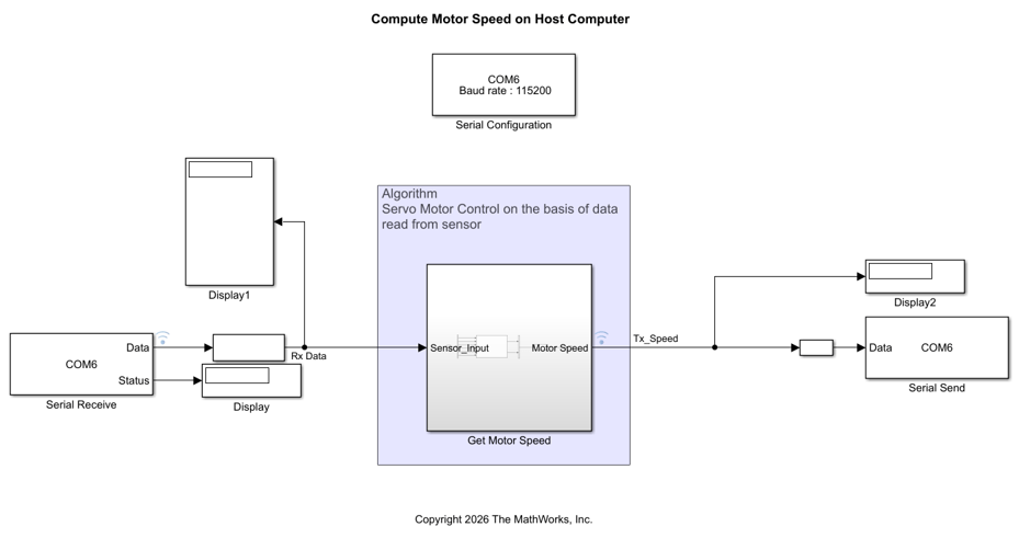
This model runs on the host computer and performs the following functions.
1. Setup serial communication — The Serial Configuration (Instrument Control Toolbox) block establishes communication on COM6 of the host computer with a baud rate of 115200.
2. Receive IMU data — The Serial Receive (Instrument Control Toolbox) block collects IMU sensor data sent from the Arduino hardware over the configured serial connection.
3. Process sensor data and compute motor command — The Get Motor Speed subsystem calculates the motor speed commands based on the sensor data. The subsystem uses the algorithm described in Algorithm for Motor Speed Computation section of this example.
4. Visualize data — The model logs the incoming sensor data and the computed motor speeds for real-time visualization using the Simulation Data Inspector app.
5. Transmit commands to Arduino — The Serial Send (Instrument Control Toolbox) block transmits the calculated motor speed and direction commands back to the Arduino hardware.
In the arduinoHostSerialSetMotorSpeed model, in the Simulation tab, set Stop Time to Inf. To synchronize the real-time communication with the Arduino hardware, select Run > Simulation Pacing. In the Simulation Pacing Options dialog box, select Enable pacing to slow down simulation and use the slider to adjust the simulation pacing.
Algorithm for Motor Speed Computation
The following diagram shows the Get Motor Speed subsystem. The MATLAB Function block calls the custom function compute_motor_command.
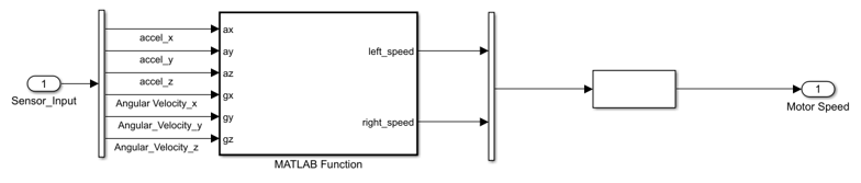
compute_motor_command accepts the IMU sensor data and calculates the speed commands for the left and right motors. This function translates sensor data into actionable commands for the motor, enabling the device to balance, move, turn, and respond to its environment.
Base Speed Calculation
If the board tilts forward (|ay > threshold), the speed is positive (move forward).
If the board tilts backward (
ay < —threshold), the speed is negative (move reverse).
Turning Adjustment
If
gz > threshold, decrease the right motor speed to initiate a right turn.If
gz < —threshold, decrease the left motor speed to initiate a left turn.
Output
The result is two independent speed values, one for the left motor and one for the right motor. The arduinoHostSerialSetMotorSpeed model dynamically adjusts these values based on the board's tilt and rotation enabling both forward and reverse movement and turning.
Adjust and tune the threshold values for ay and gz in the model so that the motors react appropriately to the motion of the board during real-world operation.
Other Things to Try
Use the
arduinoTargetSERCOMInterruptmodel to exchange data over different serial or SERCOM ports on the Arduino hardware. Using different ports let you use flexible communication setups or multiple simultaneous data streams.When using SERCOM ports for data exchange, add a TX complete interrupt to trigger actions such as running the motor speed computation algorithm immediately after data transmission is over.
Expand the existing system by connecting other IMU sensors such as an ultrasonic sensor for distance measurement to provide more comprehensive environment feedback for control algorithms.