Send and Receive Data Between Arduino and Host Using Serial Communication
This example shows how to use the Serial Transmit and Serial Receive blocks from the Simulink® Support Package for Arduino® Hardware to transmit and receive data between your host computer and Arduino hardware using a USB to serial converter. When the Arduino hardware receives data, it transmits back the same data to the host. The host then displays both the transmitted and received data on the scope.
This example uses these two Simulink models.
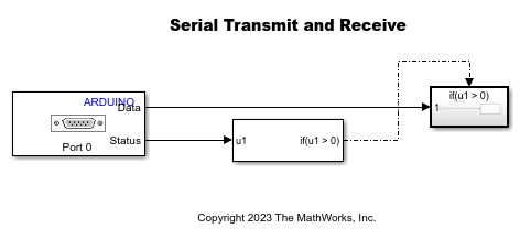
arduino_host_serial_comm- This host model contains Serial Receive (Instrument Control Toolbox) and Serial Send (Instrument Control Toolbox) blocks is at the transmitting end of the serial communication. This model transmits the counter data and receives the same counter data from the Arduino board that is at the receiving end of the serial communication.arduino_serial_comm- This model is at the receiving end of the serial communication that receives the counter data from the host Simulink model and transmit the same data back to the host.
Prerequisites
For more information on how to use the Simulink Support Package for Arduino Hardware to run a Simulink model on your Arduino board, see Get Started with Arduino Hardware. For more information on how to set up the Arduino hardware for serial communication, see Use Serial Communication with Arduino Hardware.
Required Hardware
Any Arduino hardware board
USB to serial device, for example, FTDI USB to serial device
Connecting wires
Install USB to Serial Device Driver
Follow these instructions to install a USB to serial FTDI driver.
Connect your system to the Internet, and then connect an FTDI device. If your system is connected to the Internet, the FTDI driver installs automatically once the FTDI device is plugged in.
Follow the installation guides to manually install the FTDI drivers.
Connect Arduino and USB to Serial Adaptor
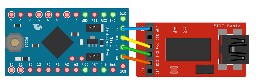
To align the TX and RX pins correctly, as shown in the diagram, connect the TX on the USB to serial device to RX on the Arduino board and RX on the USB to serial device to TX on the Arduino board. If these are misaligned, the USB to serial device can go undiscovered.
View Arduino COM Ports on Host
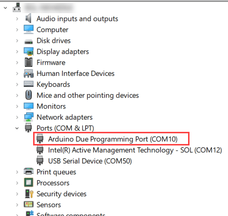
To view the list of the available Arduino COM ports on your host computer, go to Start > Control Panel > Device Manager > Ports (COM & LPT). Enter this COM port value in the Port parameter in the block masks for the blocks used in this Simulink model. The COM ports shown in this figure is for illustration purpose and might vary for your host computer.
Configure arduino_host_serial_comm Simulink Model and Calibrate Parameters
Open the arduino_host_serial_comm Simulink model.
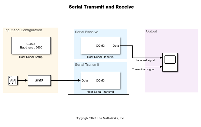
Configure the Serial Receive (Instrument Control Toolbox), Serial Send (Instrument Control Toolbox), and Serial Configuration (Instrument Control Toolbox) blocks with these parameters.
Set Baud rate to
9600.Set Block sample time to
0.001seconds.
Configure arduino_serial_comm Simulink Model and Calibrate Parameters
Open the arduino_serial_comm Simulink model.
In the Configuration Parameters dialog box of the arduino_host_serial_comm Simulink model, go to Hardware Implementation > Target hardware resources > Serial port properties and set the Serial 3 baud rate to 9600.
Configure the Serial Receive block to receive data without header and terminator at a sample time of 0.1 seconds.
The If Action Subsystem subsystem in the arduino_serial_comm Simulink model is enabled when the length of the data on the serial port is greater than zero. In this subsystem, configure the Serial Transmit to transmit data without header and terminator and Send mode as write.
Build and Deploy arduino_serial_comm Simulink Model on Arduino Hardware
On the Hardware tab of the arduino_serial_comm Simulink model, in the Deploy section, click Build, Deploy & Start.
Run arduino_host_serial_comm Simulink Model
On the arduino_host_serial_comm Simulink Model, in the Simulation tab, set the Stop Time to Inf and click the Run drop-down. Select Simulation Pacing to ensure the real-time communication with the target Arduino hardware.
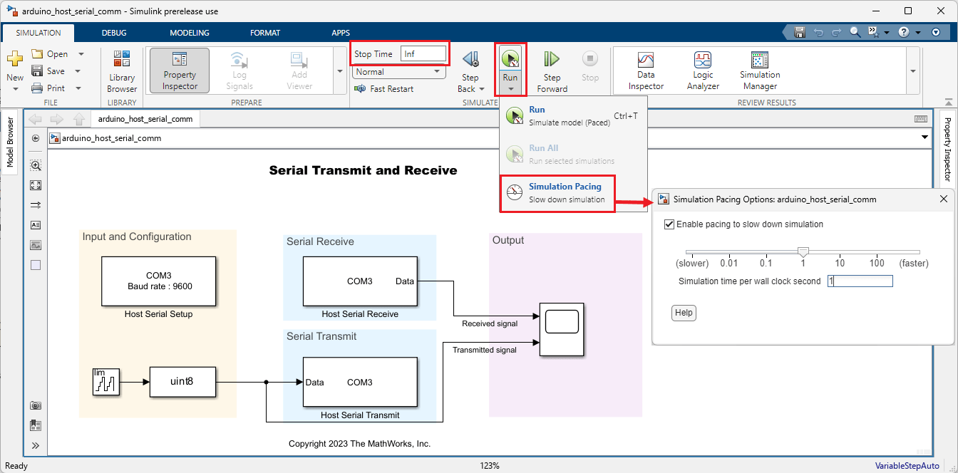
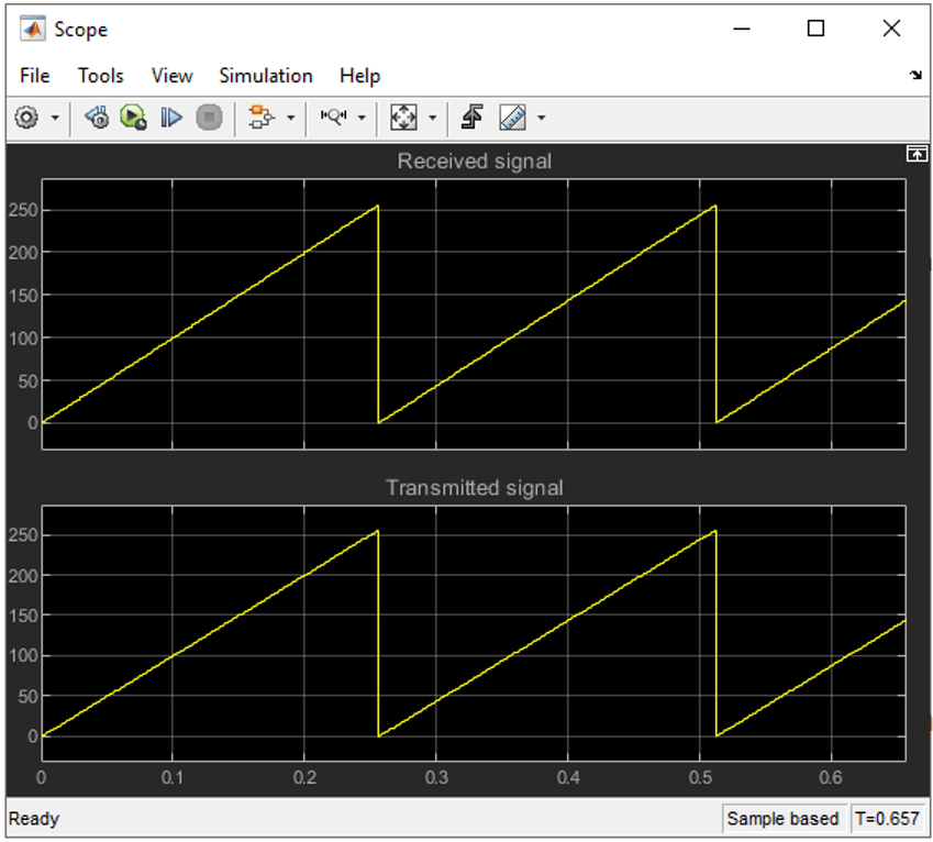
Open the Scope display and compare the serial data that the Arduino hardware receives from the host computer.
See Also
Send and Receive Data of Variable Lengths Using Arduino Serial Communication Blocks