Simulate Multiple Referenced Model Instances in Normal Mode
Multiple Model blocks can reference the same model. Each Model block that references the same model creates an instance of the referenced model in the model hierarchy.
A referenced model instance simulates in normal mode when both of these conditions apply:
The corresponding Model block has its Simulation Mode block parameter set to
Normal.The top model and any intermediate Model blocks are configured to simulate in normal mode.
For additional requirements, see Model Reference Requirements and Limitations.
When you simulate multiple referenced model instances in normal mode, only one instance has normal mode visibility.
Normal Mode Visibility
All instances of a referenced model that simulate in normal mode are part of the simulation. However, only one normal-mode instance of the referenced model supports all data visualizations. For example, scopes and port value labels display data for only the instance that has normal mode visibility enabled. To view simulation results for all instances of the referenced model, use the Simulation Data Inspector. To view instance-specific data for each instance of the model that simulates in normal mode, use Display blocks in the referenced model.
To set normal mode visibility, in the Simulink® Toolstrip, on the Simulation tab, click the down arrow on the far right of the Prepare section. In the gallery, under Signal Monitoring, click Normal Mode Visibility. This setting determines the instance that has normal mode visibility enabled. If you do not specify normal mode visibility for an instance of a referenced model, the software selects which instance of the referenced model has normal mode visibility enabled.
Examine Multiple Referenced Model Instances
Open the example project. The project opens the
MultiCounter model at startup.
openExample("simulink_features/ComponentBasedModelingUsingModelReferenceExample")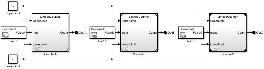
The MultiCounter model contains Model blocks named
CounterA, CounterB, and
CounterC. Each Model block references the
LimitedCounter model.
Before you compile a model, each Model block icon has white or black corners. The different corner colors indicate the simulation mode.
White corners — Normal mode
Black corners — Accelerator mode
After you compile a model, each Model block icon has white, gray, or black corners. The different corner colors indicate the simulation mode and normal mode visibility setting.
White corners — Normal mode with normal mode visibility enabled
Gray corners — Normal mode with normal mode visibility disabled
Black corners — Accelerator mode
To compile the model, in the Simulink Toolstrip, on the Modeling tab, click Update Model. Alternatively, enter this command.
set_param("MultiCounter",SimulationCommand="update")
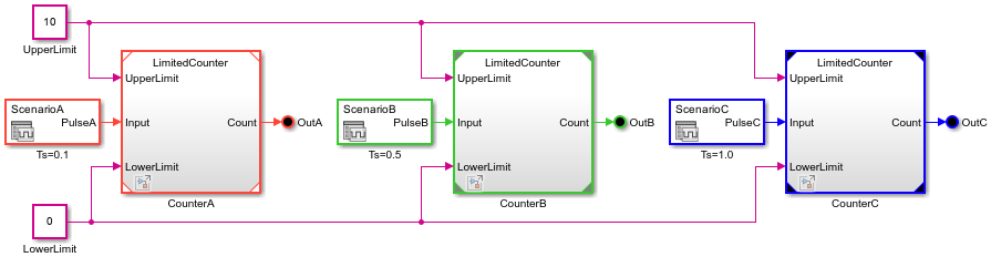
In this example, the Model block icon corner colors indicate:
The Model block named
CounterAsimulates in normal mode with normal mode visibility enabled.The Model block named
CounterBsimulates in normal mode with normal mode visibility disabled.The Model block named
CounterCsimulates in accelerator mode.
Sample time colors indicate that each Model block uses a different sample time.
Double-click the Model block named CounterA.
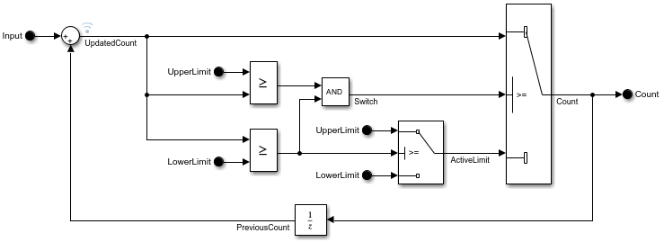
In the referenced model, the signal named UpdatedCount is marked
for logging.
Simulate the model hierarchy.
simout = sim("MultiCounter");To view the logged data for each instance of the referenced model, open the Simulation Data Inspector. In the Simulink Toolstrip, on the Simulation tab, click Data Inspector. Then, select the signals of interest.
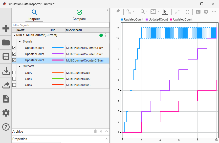
Each instance of the referenced model has different data for the signal named
UpdatedCount because of their different sample times.
Determine Which Instance Has Normal Mode Visibility Enabled
After you compile a model, you can determine whether an instance has normal mode visibility enabled by inspecting the corners of the Model block icon. When the corners are white, the instance has normal mode visibility enabled. For a large model hierarchy, finding this instance based on the Model block icons can be time consuming. Instead, use these programmatic parameters:
ModelReferenceNormalModeVisibilityBlockPath— For a referenced model, find the Model block that has normal mode visibility enabled.CompiledModelBlockNormalModeVisibility— For all referenced models in a model hierarchy, find the Model blocks that have normal mode visibility enabled.
For example, open the project named ModelReferenceHierarchy.
openProject("ModelReferenceHierarchy");The project opens a model hierarchy with sldemo_mdlref_depgraph as the top model.
Suppose you want to find the Model block that references the sldemo_mdlref_F2C model and has normal mode visibility enabled.
Update the top model.
set_param("sldemo_mdlref_depgraph",SimulationCommand="Update");
Get the Model block path.
get_param('sldemo_mdlref_F2C',...
'ModelReferenceNormalModeVisibilityBlockPath')
ans =
  Simulink.BlockPath
  Package: Simulink

  Block Path:
    sldemo_mdlref_depgraph/thermostat
      sldemo_mdlref_heater/Fahrenheit to Celsius

  Use the getBlock method to access block path strings from this object.

  Methods
Suppose you want to find all the Model blocks in a model hierarchy that have normal mode visibility enabled.
Execute the compilation phase of simulation by using the sldemo_mdlref_depgraph model name as a programmatic interface.
sldemo_mdlref_depgraph([],[],[],'compile');### Searching for referenced models in model 'sldemo_mdlref_depgraph'. ### Total of 5 models to build. ### Model reference simulation target for sldemo_mdlref_heat2cost is up to date. ### Model reference simulation target for sldemo_mdlref_thermostat is up to date. ### Model reference simulation target for sldemo_mdlref_house is up to date. ### Model reference simulation target for sldemo_mdlref_F2C is up to date. ### Model reference simulation target for sldemo_mdlref_outdoor_temp is up to date. Build Summary 0 of 5 models built (5 models already up to date) Build duration: 0h 0m 1.4269s
Get the Model block paths.
blocks = get_param('sldemo_mdlref_depgraph',...
'CompiledModelBlockNormalModeVisibility')
blocks = struct with fields:
       sldemo_mdlref_F2C: [1×1 Simulink.BlockPath]
    sldemo_mdlref_heater: [1×1 Simulink.BlockPath]
Inspect the Model block paths.
blocks.sldemo_mdlref_F2C
ans =
  Simulink.BlockPath
  Package: Simulink

  Block Path:
    sldemo_mdlref_depgraph/thermostat
      sldemo_mdlref_heater/Fahrenheit to Celsius

  Use the getBlock method to access block path strings from this object.

  Methods
blocks.sldemo_mdlref_heater
ans =
  Simulink.BlockPath
  Package: Simulink

  Block Path:
    sldemo_mdlref_depgraph/thermostat

  Use the getBlock method to access block path strings from this object.

  Methods
Terminate the compilation phase.
sldemo_mdlref_depgraph([],[],[],'term');Specify Which Instance Has Normal Mode Visibility Enabled
While you edit a model hierarchy, you can specify which instance of a referenced model has normal mode visibility enabled.
In the Simulink Toolstrip, on the Simulation tab, click the down arrow on the far right of the Prepare section. Then, under Signal Monitoring, click Normal Mode Visibility.
The Model Block Normal Mode Visibility dialog box opens. The normal mode instances of referenced models have check boxes.
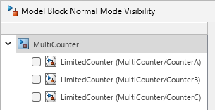
The dialog box does not display Model blocks that reference protected models, and each displayed branch of the model hierarchy stops at the first Model block that is not in normal mode.
Tip
To update the model hierarchy in the dialog box to reflect the current model hierarchy, click Refresh.
Select the instance of the model that you want to have normal mode visibility.
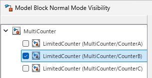
When you select an instance, you also select its parents. When you clear an instance, you also clear its children.
Tip
To open a model from the dialog box, right-click the model name. Then, click Open.
To apply the normal mode visibility setting, simulate the model hierarchy.
Alternatively, change the instance that has normal mode visibility enabled with the
ModelBlockNormalModeVisibility parameter. Set this parameter to one of
these values:
An array of
Simulink.BlockPathobjects.bp1 = Simulink.BlockPath({'TopModel/Model',... 'ReferencedModelA/Model'}); bp2 = Simulink.BlockPath({'TopModel/Model1',... 'ReferencedModelB/Model'}); bps = [bp1, bp2]; set_param('TopModel','ModelBlockNormalModeVisibility',bps);Note
When you create a
Simulink.BlockPathobject for specifying normal mode visibility:The first character vector must represent a block that is in the top model of the model reference hierarchy.
Character vectors must represent Model blocks that are in normal mode.
Character vectors that represent variant models or variant subsystems must refer to an active variant.
A cell array of cell arrays of character vectors, with the character vectors being paths to individual blocks and models.
bp1 = {'TopModel/Model','ReferencedModelA/Model'};
bp2 = {'TopModel/Model1','ReferencedModelB/Model'};
bps = {bp1, bp2};
set_param('TopModel','ModelBlockNormalModeVisibility',bps);
An empty array, to use the default selection of the instance that has normal mode visibility.
set_param('TopModel','ModelBlockNormalModeVisibility',[]);
Using an empty array is equivalent to clearing all the check boxes in the Model Block Normal Mode Visibility dialog box.