UDP Data Exchange by Using Shared Ethernet Board
This example shows how to set up two-way data exchange by using an Ethernet board that is shared with the connection between the development and target computers. Using this configuration, you can communicate between two Simulink® Real-Time™ systems, between the Simulink Real-Time and Simulink® products, or between two Simulink models. When one or both of the systems are running as a non-real-time Simulink model, be sure to set the sample time.
This example does not require configuring a dedicated Ethernet card because the example uses the connection between the development and target computers.
The example models are named slrt_ex_udpsendreceiveA and slrt_ex_udpsendreceiveB. Replace the port and IP address examples with ports and addresses as required by your network. This example uses a target computer located at IP address 192.168.7.5 and uses a development computer located at IP address 192.168.7.2.
UDP Data Transfer
The models transfer two different data sets between them, one data set from slrt_ex_udpsendreceiveA to slrt_ex_udpsendreceiveB and another data set in the opposite direction.
For this example, the inputs are generated by using Simulink® Constant blocks that use the MATLAB® random number function (rand). The Simulink® Coder[tm] software uses this function during code generation to generate random numbers. To generate the vector of uint8 (3x3), use the MATLAB® function:
uint8(255 * rand(3,3))
ans =

  3×3 uint8 matrix

   208   233    71
   231   161   139
    32    25   244
Use 255 because that is the maximum value for an unsigned 8-bit integer. The other values are generated similarly.
slrt_ex_udpsendreceiveA to slrt_ex_udpsendreceiveB
The UDP data to send is 75 bytes wide. The data to transfer is in these formats:
[3 3] of uint8 (9 bytes)
[1 1] of uint16 (2 bytes)
[2 4] of double (64 bytes)
When packed, the data is aligned on 1-byte boundaries.
slrt_ex_udpsendreceiveB to slrt_ex_udpsendreceiveA
The UDP data to be sent is 79 bytes wide. The data to transfer is in these formats:
[4 1] of single (16 bytes)
[2 2] of double (32 bytes)
[2 2] of uint32 (16 bytes)
[5 3] of int8 (15 bytes)
When packed, the data is aligned on 2-byte boundaries. A zero-valued pad byte is added during packing.
Set Up slrt_ex_udpsendreceiveA
To open the slrt_ex_udpsendreceiveA final model, in the MATLAB® Command Window type:
modelA = 'slrt_ex_udpsendreceiveA';
open_system(modelA);
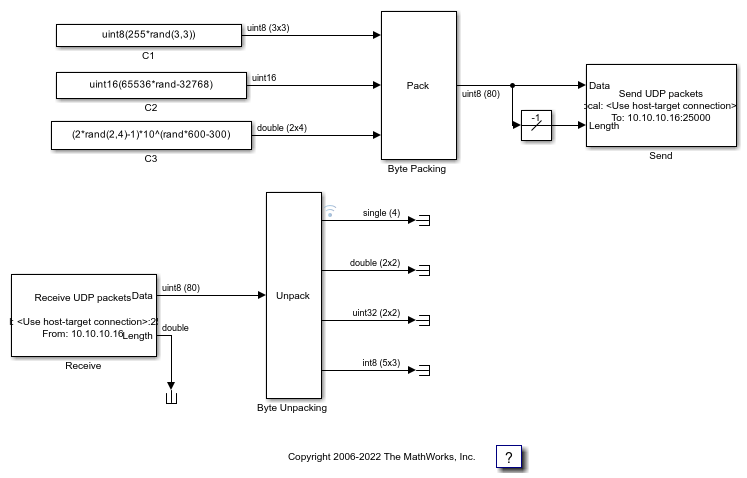
The tables list the parameters for the send and receive sides of the model.
slrt_ex_udpsendreceiveA Send Side
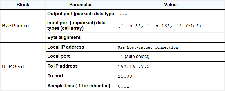
The Length input port receives the output of a Width block that calculates the width of the signal connected to the Data port.
The Byte Packing block settings match the Byte Unpacking block of slrt_ex_udpsendreceiveB.
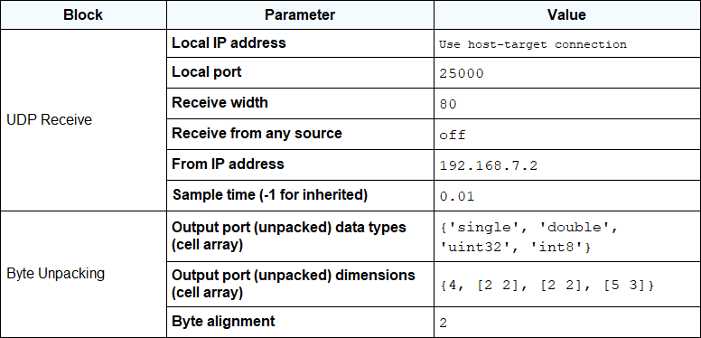
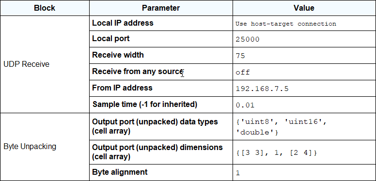
slrt_ex_udpsendreceiveA Receive Side
The second output port of the UDP Receive block is sent into a terminator. You can use this output to determine when a packet has arrived. The same is true for the outputs of the Byte Unpack block.
The Receive width of the UDP Receive block matches the output port width of the Byte Packing block in slrt_ex_udpsendreceiveB.
The Byte Unpacking block settings match the settings of the Byte Packing block of slrt_ex_udpsendreceiveB.
The number of unpacked bytes is 79. The byte alignment is 2. The Byte Unpacking block assumes that the input vector includes a pad 0 to align the vector on an even-numbered boundary.
Set Up slrt_ex_udpsendreceiveB
To open the slrt_ex_udpsendreceiveB final model, in the MATLAB Command Window type:
modelB = 'slrt_ex_udpsendreceiveB';
open_system(modelB);
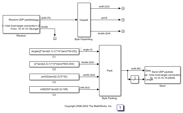
The tables list the parameters for the receive side and the send side of the model.
slrt_ex_udpsendreceiveB Receive Side
The second output port of the UDP Receive block is sent into a terminator. You can use this output to determine when a packet has arrived. The same is true for the outputs of the Byte Unpack block.
The Receive width of the UDP Receive block matches the output port width of the Byte Packing block in slrt_ex_udpsendreceiveA.
The Byte Unpacking block settings match the Byte Packing block in slrt_ex_udpsendreceiveA.
slrt_ex_udpsendreceiveB Send Side
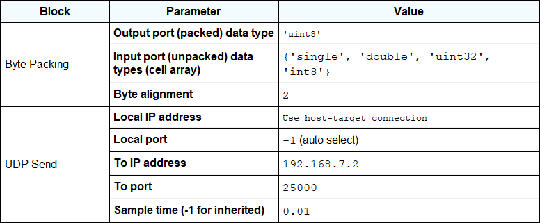
The Length input port receives the output of a Width block that calculates the width of the signal connected to the Data port.
The Byte Packing block settings match the settings of the Byte Unpacking block of slrt_ex_udpsendreceiveA.
The number of unpacked bytes is 79. The byte alignment is 2. The Byte Packing block pads the output vector with 0 to align on an even-numbered boundary.
Close Models
bdclose(modelA);
bdclose(modelB);