Control Color of Lamp on Instrument Panel by Using App Generator
This example shows how to control the color of a lamp indicator on an instrument panel that connects to a Simulink® Real-Time™ application.
The example operations are:
Open the model and build the real-time application
Open the App Generator, configure options for the Lamp components, and create instrument panel for the real-time application
Open the instrument panel in the App Designer
Run the instrument panel app and observe color cycle of lamps
Close the model and the instrument panel app
Create Target Object and Connect
Create a Target object for the default target computer and connect to the target computer.
tg = slrealtime;
connect(tg);
Build Real-Time Application
model = 'slrt_ex_lamp_instrument';
open_system(model);
modelSTF = getSTFName(tg);
set_param(model,"SystemTargetFile",modelSTF)
set_param(model,'FixedStep','.01');
evalc('slbuild(model)');

Create Instrument Panel from Real-Time Application
The App Generator can generate an instrument panel app from the model or the real-time application.
1. Open the Simulink Real-Time App Generator. In the Command Window, type: slrtAppGenerator.
2. To create an instrument panel from the real-time application MLDATX file, select New > New, then select the real-time application file slrt_ex_lamp_instrument.mldatx.
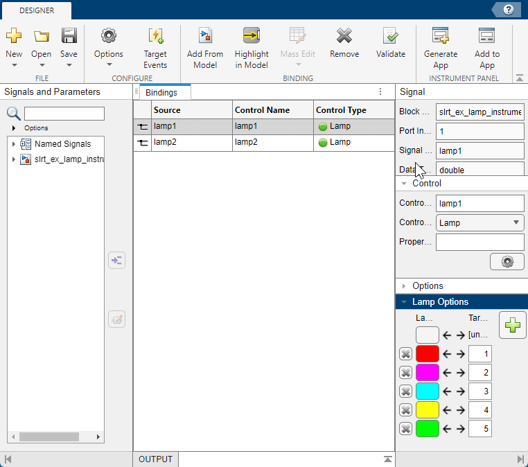
3. From the Signals and Parameters pane, select Named Signals lamp1 and lamp2. Add these to the Bindings table.
4. In the Bindings table, change the Control Type for these signals to Lamp.
5. To configure control of the lamp color for lamp1, add Lamp Colors and set Target Values in the Lamp Options pane. The App Generator generates callback code in the instrument panel app to use the signal data to select each color for the lamp.
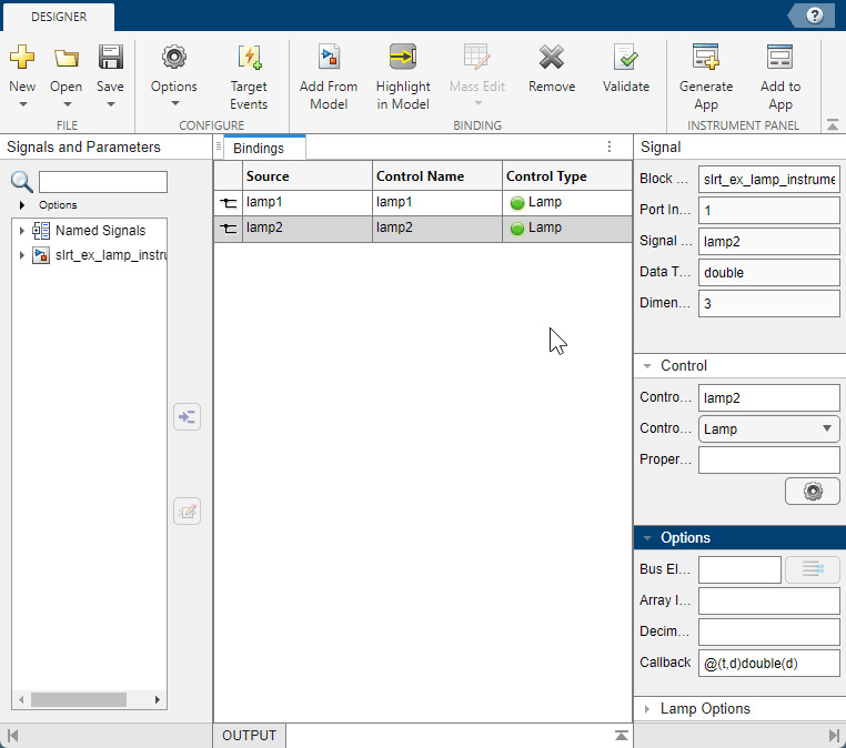
6. To configure control of the lamp color for lamp2, add Callback code @(t,d)double(d) in the Options pane. The App Generator generates callback code in the intrument panel app to use the color triplet data from the lamp2 signal to select each color for the lamp.
7. Select Generate App. Save the app as slrt_ex_lamp_instrument_slrealtime.mlapp and open the app in App Designer. The app includes default controls for the real-time application and the Lamp components that you connected.

(Optional) Examine Callback Code in App Designer
The generated app includes functions to process data from the lamp1 and lamp2 signals. These functions include:
lampBlockCB-- This function converts the input values to colors forlamp1.startupFcn-- This function executes after component creation. The function includes theconnectScalarfunction calls that connect the signals to the Lamp components.
Run Real-Time Application from the Instrument Panel
After modifying the instrument panel app, run the app slrt_ex_lamp_instrument_slrealtime-mlapp.
Use the app to load and run the real-time application.
Observe the Lamp component color changes.
Stop Real-Time Application
Use the instrument panel to stop the real-time application.
Close All Windows
bdclose('all');
You can also select a web site from the following list:
Americas
- América Latina (Español)
- Canada (English)
- United States (English)
Europe
- Belgium (English)
- Denmark (English)
- Deutschland (Deutsch)
- España (Español)
- Finland (English)
- France (Français)
- Ireland (English)
- Italia (Italiano)
- Luxembourg (English)
- Netherlands (English)
- Norway (English)
- Österreich (Deutsch)
- Portugal (English)
- Sweden (English)
- Switzerland
- United Kingdom (English)